ASRock H310CM-DVS User Manual - Page 26
USB 3.1 Gen1 Header, pin SPK_CI1
 |
View all ASRock H310CM-DVS manuals
Add to My Manuals
Save this manual to your list of manuals |
Page 26 highlights
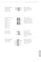
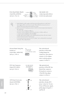
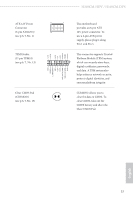
H310CM-HDV / H310CM-DVS Chassis Intrusion and Speaker Header (7-pin SPK_CI1) (see p.6, 7, No. 14) SPEAKER DUMMY DUMMY +5V DUMMY GND SIGNAL 1 Please connect the chassis intrusion and the chassis speaker to this header. Serial ATA3 Connectors (SATA3_0: see p.6, 7, No. 10) (SATA3_1: see p.6, 7, No. 11) (SATA3_2: see p.6, 7, No. 8) (SATA3_3: see p.6, 7, No. 9) SATA3_0 SATA3_2 SATA3_1 SATA3_3 These four SATA3 connectors support SATA data cables for internal storage devices with up to 6.0 Gb/s data transfer rate. USB 2.0 Header (9-pin USB_5_6) (see p.6, 7, No. 7) DUMMY GND P+ P- USB_PWR GND P+ PUSB_PWR 1 There is one USB 2.0 header on this motherboard. This USB 2.0 header can support two ports. USB 3.1 Gen1 Header (19-pin USB3_3_4) (see p.6, 7, No. 6) Vbus IntA_P2_SSRXIntA_P2_SSRX+ GND IntA_P2_SSTXIntA_P2_SSTX+ GND IntA_P2_DIntA_P2_D+ Vbus IntA_P3_SSRXIntA_P3_SSRX+ GND IntA_P3_SSTXIntA_P3_SSTX+ GND IntA_P3_DIntA_P3_D+ ID 1 There is one header on this motherboard. This USB 3.1 Gen1 header can support two ports. English 21
-
 1
1 -
2
-
3
-
4
-
5
-
6
-
7
-
8
-
9
-
10
-
11
-
12
-
13
-
14
-
15
-
16
-
17
-
18
-
19
-
20
-
 21
21 -
 22
22 -
 23
23 -
 24
24 -
 25
25 -
 26
26 -
 27
27 -
 28
28 -
 29
29 -
 30
30 -
 31
31 -
32
-
33
-
34
-
35
-
36
-
37
-
38
-
39
-
40
-
41
-
42
-
43
-
44
-
45
-
46
-
47
-
48
-
49
-
50
-
51
-
52
-
53
-
54
-
55
-
56
-
57
-
58
-
59
-
60
-
61
-
62
-
63
-
64
-
65
-
66
-
67
-
68
-
69
-
70
-
71
-
72
-
73
 |
 |
