ASRock H410M-H/M.2 SE User Manual
ASRock H410M-H/M.2 SE Manual
 |
View all ASRock H410M-H/M.2 SE manuals
Add to My Manuals
Save this manual to your list of manuals |
ASRock H410M-H/M.2 SE manual content summary:
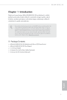
- ASRock H410M-H/M.2 SE | User Manual - Page 1
- ASRock H410M-H/M.2 SE | User Manual - Page 2
to visit ASRock's website at http://www.asrock.com; or you may contact your dealer for further information. For technical questions, please submit a support request form at https://event.asrock.com/tsd.asp ASRock Incorporation e-mail: [email protected] ASRock EUROPE B.V. e-mail: [email protected] - ASRock H410M-H/M.2 SE | User Manual - Page 3
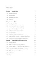
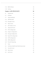
Express Slots) 16 2.5 Jumpers Setup 17 2.6 Onboard Headers and Connectors 18 2.7 M.2_SSD (NGFF) Module Installation Guide (M2_1) 22 2.8 M.2 WiFi/BT Module Installation Guide (M2_2) 24 Chapter 3 Software and Utilities Operation 26 3.1 Installing Drivers 26 3.2 ASRock Motherboard Utility - ASRock H410M-H/M.2 SE | User Manual - Page 4
3.3.3 BIOS & Drivers 34 3.3.4 Setting 35 Chapter 4 UEFI SETUP UTILITY 36 4.1 Introduction 36 4.2 EZ Mode 37 4.3 Advanced Mode 38 4.3.1 UEFI Menu Bar 38 4.3.2 Navigation Keys 39 4.4 Main Screen 40 4.5 OC Tweaker Screen 41 4.6 Advanced Screen 49 4.6.1 CPU Configuration 50 4.6.2 - ASRock H410M-H/M.2 SE | User Manual - Page 5
on ASRock's website without further notice. If you require technical support related to this motherboard, please visit our website for specific • ASRock H410M-H/M.2 SE Motherboard (Micro ATX Form Factor) • ASRock H410M-H/M.2 SE User Manual • 1 x I/O Panel Shield • 2 x Serial ATA (SATA) Data Cables ( - ASRock H410M-H/M.2 SE | User Manual - Page 6
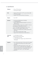
type 2230 WiFi/BT PCIe WiFi module Graphics • Intel® UHD Graphics Built-in Visuals and the VGA outputs can be supported only with processors which are GPU integrated. • Supports Intel® UHD Graphics Built-in Visuals : Intel® Quick Sync Video with AVC, MVC (S3D) and MPEG-2 Full HW Encode1, Intel - ASRock H410M-H/M.2 SE | User Manual - Page 7
Rear Panel I/O • 2 x Antenna Mounting Points • 1 x PS/2 Mouse/Keyboard Port • 1 x D-Sub Port • 1 x DisplayPort 1.2 • 1 x HDMI Port • 2 x USB 2.0 Ports (Supports ESD Protection) • 4 x USB 3.2 Gen1 Ports (Supports ESD Protection) • 1 x RJ-45 LAN Port with LED (ACT/LINK LED and SPEED LED) • HD Audio - ASRock H410M-H/M.2 SE | User Manual - Page 8
the water cooler fan of maximum 2A (24W) fan power. • 2 x Chassis/Water Pump Fan Connectors (4-pin) (Smart Fan Speed Control) * The Chassis/Water Pump Fan supports the water cooler fan of maximum 2A (24W) fan power. * CPU_FAN2/WP, CHA_FAN1/WP and CHA_FAN2/WP can auto detect if 3-pin or 4-pin fan - ASRock H410M-H/M.2 SE | User Manual - Page 9
H410M-H/M.2 SE Hardware Monitor OS Certifications • Fan Tachometer: CPU, CPU/Water Pump, Chassis/Water Pump Fans • Quiet Fan (Auto adjust chassis fan speed by CPU temperature): CPU, CPU/Water Pump, Chassis/Water Pump Fans • Fan Multi-Speed Control: CPU, CPU/Water Pump, Chassis/ Water Pump Fans • - ASRock H410M-H/M.2 SE | User Manual - Page 10
1.3 Motherboard Layout 6 English - ASRock H410M-H/M.2 SE | User Manual - Page 11
No. Description 1 ATX 12V Power Connector (ATX12V1) 2 CPU Fan Connector (CPU_FAN1) 3 2 x 288-pin DDR4 DIMM Slots (DDR4_A1, DDR4_B1) 4 Chassis/Water Pump Fan Connector (CHA_FAN1/WP) 5 ATX Power Connector (ATXPWR1) 6 USB 3.2 Gen1 Header (USB32_7_8) 7 SATA3 Connector (SATA3_0) (Upper) 8 SATA3 Connector - ASRock H410M-H/M.2 SE | User Manual - Page 12
1.4 I/O Panel 3 1 2 4 11 10 9 No. Description 1 USB 2.0 Ports (USB_12) 2 LAN RJ-45 Port* 3 Line In (Light Blue)** 4 Front Speaker (Lime)** 5 Microphone (Pink)** 6 USB 3.2 Gen1 Ports (USB32_34) 8 7 6 5 No. Description 7 USB 3.2 Gen1 Ports (USB32_12) 8 PS/2 Mouse/Keyboard Port 9 HDMI Port - ASRock H410M-H/M.2 SE | User Manual - Page 13
H410M-H/M.2 SE Chapter 2 Installation This is a Micro ATX form factor motherboard. Before you install the motherboard, study the configuration of your chassis to ensure that the motherboard fits into it. Pre-installation Precautions Take note of the following precautions before you install - ASRock H410M-H/M.2 SE | User Manual - Page 14
2.1 Installing the CPU 1. Before you insert the 1200-Pin CPU into the socket, please check if the PnP cap is on the socket, if the CPU surface is unclean, or if there are any bent pins in the socket. Do not force to insert the CPU into the socket if above situation is found. Otherwise, the CPU will - ASRock H410M-H/M.2 SE | User Manual - Page 15
H410M-H/M.2 SE 3 4 5 11 English - ASRock H410M-H/M.2 SE | User Manual - Page 16
Please save and replace the cover if the processor is removed. The cover must be placed if you wish to return the motherboard for after service. 12 English - ASRock H410M-H/M.2 SE | User Manual - Page 17
2.2 Installing the CPU Fan and Heatsink H410M-H/M.2 SE 1 2 CPU_FAN 13 English - ASRock H410M-H/M.2 SE | User Manual - Page 18
2.3 Installing Memory Modules (DIMM) This motherboard provides two 288-pin DDR4 (Double Data Rate 4) DIMM slots, and supports Dual Channel Memory Technology. 1. For dual channel configuration, you always need to install identical (the same brand, speed, size and chip-type) DDR4 DIMM pairs. 2. - ASRock H410M-H/M.2 SE | User Manual - Page 19
H410M-H/M.2 SE 1 2 3 15 English - ASRock H410M-H/M.2 SE | User Manual - Page 20
2.4 Expansion Slots (PCI Express Slots) There are 2 PCI Express slots on the motherboard. Before installing an expansion card, please make sure that the power supply is switched off or the power cord is unplugged. Please read the documentation of the expansion card and make necessary hardware - ASRock H410M-H/M.2 SE | User Manual - Page 21
H410M-H/M.2 SE 2.5 Jumpers Setup The illustration shows how jumpers are setup. When the jumper cap is placed on the pins, the jumper is "Short". If no jumper cap is placed on the pins, the jumper is "Open". Clear CMOS Jumper (CLRMOS1) (see p.6, No. 18) 2-pin Jumper Short: Clear CMOS Open: Default - ASRock H410M-H/M.2 SE | User Manual - Page 22
2.6 Onboard Headers and Connectors Onboard headers and connectors are NOT jumpers. Do NOT place jumper caps over these headers and connectors. Placing jumper caps over the headers and connectors will cause permanent damage to the motherboard. System Panel Header (9-pin PANEL1) (see p.6, No. 11) - ASRock H410M-H/M.2 SE | User Manual - Page 23
: see p.6, No. 8) (Lower) (SATA3_2: see p.6, No. 9) (Upper) (SATA3_3: see p.6, No. 10) (Lower) SATA3_2 SATA3_0 SATA3_3 SATA3_1 These four SATA3 connectors support SATA data cables for internal storage devices with up to 6.0 Gb/s data transfer rate. USB 2.0 Headers (9-pin USB_3_4) (see p.6, No. 15 - ASRock H410M-H/M.2 SE | User Manual - Page 24
Jack Sensing, but the panel wire on the chassis must support HDA to function correctly. Please follow the instructions in our manual and chassis manual to install your system. 2. If you use an AC'97 audio panel, please install it to the front panel audio header by the steps below: A. - ASRock H410M-H/M.2 SE | User Manual - Page 25
power cable connected is for the CPU and not the graphics card. Do not plug the PCIe power cable to this connector. This COM1 header supports a serial port module. English 21 - ASRock H410M-H/M.2 SE | User Manual - Page 26
2.7 M.2_SSD (NGFF) Module Installation Guide (M2_1) The M.2 is a small size and versatile card edge connector that aims to replace mPCIe and mSATA. The Ultra M.2 Socket (M2_1) supports M Key type 2260/2280 M.2 SATA3 6.0 Gb/s module and M.2 PCI Express module up to Gen3 x4 (32 Gb/s). Installing the - ASRock H410M-H/M.2 SE | User Manual - Page 27
to secure the module into place. Please do not overtighten the screw as this might damage the module. For the latest updates of M.2 SSD module support list, please visit our website for details: http://www.asrock.com 23 - ASRock H410M-H/M.2 SE | User Manual - Page 28
Module Installation Guide (M2_2) The M.2, also known as the Next Generation Form Factor (NGFF), is a small size and versatile card edge connector that aims to replace mPCIe and mSATA. The M.2 Socket (Key E) supports type 2230 WiFi/BT PCIe WiFi module. * The M.2 socket does not support SATA M.2 SSDs - ASRock H410M-H/M.2 SE | User Manual - Page 29
A A 20o A H410M-H/M.2 SE Step 3 Gently insert the WiFi/BT PCIe WiFi module into the M.2 slot. Please be aware that the module only fits in one orientation. Step 4 Tighten the screw with a screwdriver to secure the module into place. Please do not overtighten the screw as this might damage the - ASRock H410M-H/M.2 SE | User Manual - Page 30
CD that comes with the motherboard contains necessary drivers and useful utilities that enhance the motherboard's features. Running The Support CD To begin using the support CD, insert the CD into your CD-ROM drive. The CD automatically displays the Main Menu if "AUTORUN" is enabled in your computer - ASRock H410M-H/M.2 SE | User Manual - Page 31
H410M-H/M.2 SE 3.2 ASRock Motherboard Utility (A-Tuning) ASRock Motherboard Utility (A-Tuning) is ASRock's multi purpose software suite with a new interface, more new features and improved utilities. 3.2.1 Installing ASRock Motherboard Utility (A-Tuning) ASRock Motherboard Utility (A-Tuning) can be - ASRock H410M-H/M.2 SE | User Manual - Page 32
System Info View information about the system. *The System Browser tab may not appear for certain models. FAN-Tastic Tuning Configure up to five different fan speeds using the graph. The fans will automatically shift to the next speed level when the assigned temperature is met. 28 English - ASRock H410M-H/M.2 SE | User Manual - Page 33
H410M-H/M.2 SE Settings Configure ASRock ASRock Motherboard Utility (A-Tuning). Click to select "Auto run at Windows Startup" if you want ASRock Motherboard Utility (A-Tuning) to be launched when you start up the Windows operating system. 29 English - ASRock H410M-H/M.2 SE | User Manual - Page 34
Shop is an online store for purchasing and downloading software applications for your ASRock computer. You can quickly and easily install various apps and support utilities. With ASRock Live Update & APP Shop, you can optimize your system and keep your motherboard up to date simply with a few clicks - ASRock H410M-H/M.2 SE | User Manual - Page 35
H410M-H/M.2 SE 3.3.2 Apps When the "Apps" tab is selected, you will see all the available apps on screen for you to download. Installing an App Step 1 Find the app you want to install. The most recommended app appears on the left side of the screen. The other various apps are shown on the right. - ASRock H410M-H/M.2 SE | User Manual - Page 36
Step 3 If you want to install the app, click on the red icon to start downloading. Step 4 When installation completes, you can find the green "Installed" icon appears on the upper right corner. English To uninstall it, simply click on the trash can icon . *The trash icon may not appear for - ASRock H410M-H/M.2 SE | User Manual - Page 37
H410M-H/M.2 SE Upgrading an App You can only upgrade the apps you have already installed. When there is an available new version for your app, you will find the mark of "New Version" appears below the installed app icon. Step 1 Click on the app icon to see more details. Step 2 Click on the yellow - ASRock H410M-H/M.2 SE | User Manual - Page 38
3.3.3 BIOS & Drivers Installing BIOS or Drivers When the "BIOS & Drivers" tab is selected, you will see a list of recommended or critical updates for the BIOS or drivers. Please update them all soon. Step 1 Please check the item information before update. Click on Step 2 to see more details. - ASRock H410M-H/M.2 SE | User Manual - Page 39
H410M-H/M.2 SE 3.3.4 Setting In the "Setting" page, you can change the language, select the server location, and determine if you want to automatically run the ASRock Live Update & APP Shop on Windows startup. 35 English - ASRock H410M-H/M.2 SE | User Manual - Page 40
Chapter 4 UEFI SETUP UTILITY 4.1 Introduction This section explains how to use the UEFI SETUP UTILITY to configure your system. You may run the UEFI SETUP UTILITY by pressing or right after you power on the computer, otherwise, the Power-On-Self-Test (POST) will continue with its test - ASRock H410M-H/M.2 SE | User Manual - Page 41
H410M-H/M.2 SE 4.2 EZ Mode The EZ Mode screen appears when you enter the BIOS setup program by default. EZ mode is a dashboard which contains multiple readings of the system's current status. You can check the most crucial information of your system, such as CPU speed, DRAM frequency, SATA - ASRock H410M-H/M.2 SE | User Manual - Page 42
4.3 Advanced Mode The Advanced Mode provides more options to configure the BIOS settings. Refer to the following sections for the detailed configurations. To access the EZ Mode, press or click the "EZ Mode" button at the upper right corner of the screen. 4.3.1 UEFI Menu Bar The top of the - ASRock H410M-H/M.2 SE | User Manual - Page 43
H410M-H/M.2 SE 4.3.2 Navigation Keys Use < > key or < > key to choose among the selections on the menu bar, and use < > key or < > key to move the cursor up or down to select items, then press to get into the sub screen. You can also use the mouse to click your required item. Please check - ASRock H410M-H/M.2 SE | User Manual - Page 44
4.4 Main Screen When you enter the UEFI SETUP UTILITY, the Main screen will appear and display the system overview. The availability and location of BIOS settings can be different for different models and BIOS versions. My Favorite Display your collection of BIOS items. Press F5 to add/remove your - ASRock H410M-H/M.2 SE | User Manual - Page 45
4.5 OC Tweaker Screen In the OC Tweaker screen, you can set up overclocking features. H410M-H/M.2 SE Because the UEFI software is constantly being updated, the following UEFI setup screens and descriptions are for reference purpose only, and they may not exactly match what you see on your screen. - ASRock H410M-H/M.2 SE | User Manual - Page 46
Intel Speed Shift Technology Enable/Disable Intel Speed Shift Technology support. Enabling will expose the CPPC v2 interface to allow for controlled P-states. Intel Thermal Velocity Boost Voltage Optimizations This service controls thermal based voltage optimizations for processors that implment the - ASRock H410M-H/M.2 SE | User Manual - Page 47
H410M-H/M.2 SE DRAM Reference Clock Select Auto for optimized settings. DRAM Frequency If [Auto] is selected, the motherboard will detect the memory module(s) inserted and assign the appropriate frequency automatically. Primary Timing CAS# Latency (tCL) The time between sending a column address to - ASRock H410M-H/M.2 SE | User Manual - Page 48
RAS to RAS Delay (tRRD_S) The number of clocks between two rows activated in different banks of the same rank. Write to Read Delay (tWTR_L) The number of clocks between the last valid write operation and the next read command to the same internal bank. Write to Read Delay (tWTR_S) The number of - ASRock H410M-H/M.2 SE | User Manual - Page 49
tRDRD_dd Configure between module read to read delay. tRDWR_sg Configure between module read to write delay. tRDWR_dg Configure between module read to write delay. tRDWR_dr Configure between module read to write delay. tRDWR_dd Configure between module read to write delay. tWRRD_sg Configure between - ASRock H410M-H/M.2 SE | User Manual - Page 50
. ODT WR (B1) Configure the memory on die termination resistors' WR for channel B1. ODT NOM (A1) Use this to change ODT (CH A1) Auto/Manual settings. The default is [Auto]. 46 English - ASRock H410M-H/M.2 SE | User Manual - Page 51
ODT NOM (B1) Use this to change ODT (CH B1) Auto/Manual settings. The default is [Auto]. ODT PARK (A1) Configure the performing realtime memory timing changes after MRC_DONE. Command Tristate Configure the Command Tristate Support. Exit On Failure Configure the Exit On Failure for MRC training steps. - ASRock H410M-H/M.2 SE | User Manual - Page 52
VCCSA Voltage Configure the voltage for the VCCSA. PCH Voltage Configure the chipset voltage. VCCST Voltage Configure the voltage for the VCCST. Save User Default Type a profile name and press enter to save your settings as user default. Load User Default Load previously saved user defaults. Save - ASRock H410M-H/M.2 SE | User Manual - Page 53
UEFI setup utility. Full HD UEFI When [Auto] is selected, the resolution will be set to 1920 x 1080 if the monitor supports Full HD resolution. If the monitor does not support Full HD resolution, then the resolution will be set to 1024 x 768. When [Disable] is selected, the resolution will be set - ASRock H410M-H/M.2 SE | User Manual - Page 54
on threaded software is improved. Active Processor Cores Select the number of cores to enable in each processor package. CPU C States Support Enable CPU C States Support for power saving. It is recommended to keep C3, C6 and C7 all enabled for better power saving. Enhanced Halt State (C1E - ASRock H410M-H/M.2 SE | User Manual - Page 55
Enable CPU, PCIe, Memory, Graphics C State Support for power saving. CFG Lock This item allows you to disable or enable the CFG Lock. C6DRAM Enable/Disable moving of DRAM contents to PRM - ASRock H410M-H/M.2 SE | User Manual - Page 56
primary VGA. Above 4G Decoding Enable or disable 64bit capable Devices to be decoded in Above 4G Address Space (only if the system supports 64 bit PCI decoding). VT-d Intel® Virtualization Technology for Directed I/O helps your virtual machine monitor better utilize hardware by improving application - ASRock H410M-H/M.2 SE | User Manual - Page 57
This option enables/disables the control of ASPM on CPU side of the DMI Link. PCH DMI ASPM Support This option enables/disables the ASPM support for all PCH DMI devices. Share Memory Configure the size of memory that is allocated to the integrated graphics processor when the system boots up. - ASRock H410M-H/M.2 SE | User Manual - Page 58
Onboard WAN Device Enable/disable the onboard WAN device. Deep Sleep Configure deep sleep mode for power saving when the computer is shut down. Restore on AC/Power Loss Select the power state after a power failure. If [Power Off] is selected, the power will remain off when the power recovers. If [ - ASRock H410M-H/M.2 SE | User Manual - Page 59
Enable/disable the SATA controllers. SATA Mode Selection AHCI: Supports new features that improve performance. RAID: Combine multiple disk low power state during periods of inactivity to save power. It is only supported by AHCI mode. Hard Disk S.M.A.R.T. S.M.A.R.T stands for Self-Monitoring, Analysis - ASRock H410M-H/M.2 SE | User Manual - Page 60
4.6.4 Super IO Configuration Serial Port Enable or disable the Serial port. Serial Port Address Select the address of the Serial port. Parallel Port Enable or disable the Parallel port. Change Settings Select the address of the Parallel port. Device Mode Select the device mode according to your - ASRock H410M-H/M.2 SE | User Manual - Page 61
to RAM Select disable for ACPI suspend type S1. It is recommended to select auto for ACPI S3 power saving. PS/2 Keyboard S4/S5 Wakeup Support Allow the system to be waked up by a PS/2 Keyboard in S4/S5. PCIE Devices Power On Allow the system to be waked up by - ASRock H410M-H/M.2 SE | User Manual - Page 62
compatibility issues it is recommended to disable legacy USB support. Select UEFI Setup Only to support USB devices under the UEFI setup and Windows/Linux operating systems only. XHCI Hand-off This is a workaround for OSes without XHCI hand-off support. The XHCI ownership change should be claimed by - ASRock H410M-H/M.2 SE | User Manual - Page 63
4.6.7 Trusted Computing H410M-H/M.2 SE Security Device Support Enable or disable BIOS support for security device. English 59 - ASRock H410M-H/M.2 SE | User Manual - Page 64
4.7 Tools UEFI Tech Service Contact ASRock Tech Service if you are having trouble with your PC. Please setup network configuration before using UEFI Tech Service. Easy RAID Installer Easy RAID Installer helps you to copy the RAID driver from the support CD to your USB storage device. After copying - ASRock H410M-H/M.2 SE | User Manual - Page 65
H410M-H/M.2 SE 4.8 Hardware Health Event Monitoring Screen This section allows you to monitor the status of the hardware on your system, including the parameters of the CPU temperature, motherboard temperature, fan speed and voltage. Fan Tuning Measure Fan Min Duty Cycle. Fan-Tastic Tuning Select a - ASRock H410M-H/M.2 SE | User Manual - Page 66
CPU Fan 2 Control Mode Select PWM mode or DC mode for CPU_FAN2. CPU Fan 2 Setting Select a fan mode for CPU_FAN2, or choose Customize to set 5 CPU temperatures and assign a respective fan speed for each temperature. CPU Fan 2 Temp Source Select a fan temperature source for CPU_FAN2. CPU Fan 2 Step - ASRock H410M-H/M.2 SE | User Manual - Page 67
H410M-H/M.2 SE Chassis Fan 2 Setting Select a fan mode for CHA_FAN2, or choose Customize to set 5 CPU temperatures and assign a respective fan speed for each temperature. Chassis Fan 2 Temp Source Select a fan temperature source for Chassis Fan 2. Chassis Fan 2 Step Up Set the value of Chassis Fan 2 - ASRock H410M-H/M.2 SE | User Manual - Page 68
settings in the UEFI Setup Utility. Leave it blank and press enter to remove the password. Secure Boot Use this item to enable or disable support for Secure Boot. 64 English - ASRock H410M-H/M.2 SE | User Manual - Page 69
priority. Fast Boot Fast Boot minimizes your computer's boot time. In fast mode you may not boot from an USB storage device. The VBIOS must support UEFI GOP if you are using an external graphics card. Please notice that Ultra Fast mode will boot so fast that the only way to - ASRock H410M-H/M.2 SE | User Manual - Page 70
If the computer fails to boot for a number of times the system automatically restores the default settings. CSM (Compatibility Support Module) CSM Enable to launch the Compatibility Support Module. Please do not disable unless you're running a WHCK test. Launch PXE OpROM Policy Select UEFI only to - ASRock H410M-H/M.2 SE | User Manual - Page 71
H410M-H/M.2 SE Launch Storage OpROM Policy Select UEFI only to run those that support UEFI option ROM only. Select Legacy only to run those that support legacy option ROM only. Select Do not launch to not execute both legacy and UEFI option ROM. Other PCI Device ROM Priority For PCI devices - ASRock H410M-H/M.2 SE | User Manual - Page 72
4.11 Exit Screen Save Changes and Exit When you select this option the following message, "Save configuration changes and exit setup?" will pop out. Select [OK] to save changes and exit the UEFI SETUP UTILITY. Discard Changes and Exit When you select this option the following message, "Discard - ASRock H410M-H/M.2 SE | User Manual - Page 73
Version 1.0 Published December 2022 Copyright©2022 ASRock INC. All rights reserved. Copyright Notice: No part of this documentation may be reproduced, transcribed, transmitted, or translated in any language, in any form or by any means, except duplication of documentation by the purchaser for backup - ASRock H410M-H/M.2 SE | User Manual - Page 74
in, and licensed in accordance with, an enclosed license.txt file or other text or file. (e) Intel has no obligation to provide any support, technical assistance or updates for the Software. OWNERSHIP OF SOFTWARE AND COPYRIGHTS. Title to all copies of the Software remains with Intel or its - ASRock H410M-H/M.2 SE | User Manual - Page 75
U.S. GOVERNMENT RESTRICTED RIGHTS. The Software is a commercial item (as defined in 48 C.F.R. 2.101) consisting of commercial computer software and commercial computer software documentation (as those terms are used in 48 C.F.R. 12.212), consistent with 48 C.F.R. 12.212 and 48 C.F.R 227.7202-1 - ASRock H410M-H/M.2 SE | User Manual - Page 76
WARNING THIS PRODUCT CONTAINS A BUTTOON BATTERY If swallowed, a button battery can cause serious injury or death. Please keep batteries out of sight or reach of children. CALIFORNIA, USA ONLY The Lithium battery adopted on this motherboard contains Perchlorate, a toxic substance controlled in
-
 1
1 -
 2
2 -
 3
3 -
 4
4 -
 5
5 -
 6
6 -
 7
7 -
8
-
9
-
10
-
11
-
12
-
13
-
14
-
15
-
16
-
17
-
18
-
19
-
20
-
21
-
22
-
23
-
24
-
25
-
26
-
27
-
28
-
29
-
30
-
31
-
32
-
33
-
34
-
35
-
36
-
37
-
38
-
39
-
40
-
41
-
42
-
43
-
44
-
45
-
46
-
47
-
48
-
49
-
50
-
51
-
52
-
53
-
54
-
55
-
56
-
57
-
58
-
59
-
60
-
61
-
62
-
63
-
64
-
65
-
66
-
67
-
68
-
69
-
70
-
71
-
72
-
73
-
74
-
75
-
76
 |
 |
