ASRock H410M-H/M.2 SE User Manual - Page 25
Warning: Please make, sure that the power cable, connected is for the CPU, and not the graphics,
 |
View all ASRock H410M-H/M.2 SE manuals
Add to My Manuals
Save this manual to your list of manuals |
Page 25 highlights
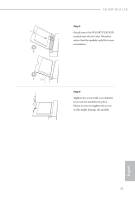
H410M-H/M.2 SE ATX Power Connector (24-pin ATXPWR1) (see p.6, No. 5) ATX 12V Power Connector (8-pin ATX12V1) (see p.6, No. 1) Serial Port Header (9-pin COM1) (see p.6, No. 17) 12 24 1 13 8 5 4 1 RRXD1 DDTR#1 DDSR#1 CCTS#1 1 RRI#1 RRTS#1 GND TTXD1 DDCD#1 This motherboard provides a 24-pin ATX power connector. To use a 20pin ATX power supply, please plug it along Pin 1 and Pin 13. This motherboard provides a 8-pin ATX 12V power connector. To use a 4-pin ATX power supply, please plug it along Pin 1 and Pin 5. *Warning: Please make sure that the power cable connected is for the CPU and not the graphics card. Do not plug the PCIe power cable to this connector. This COM1 header supports a serial port module. English 21
-
 1
1 -
2
-
3
-
4
-
5
-
6
-
7
-
8
-
9
-
10
-
11
-
12
-
13
-
14
-
15
-
16
-
17
-
18
-
19
-
 20
20 -
 21
21 -
 22
22 -
 23
23 -
 24
24 -
 25
25 -
 26
26 -
 27
27 -
 28
28 -
 29
29 -
 30
30 -
31
-
32
-
33
-
34
-
35
-
36
-
37
-
38
-
39
-
40
-
41
-
42
-
43
-
44
-
45
-
46
-
47
-
48
-
49
-
50
-
51
-
52
-
53
-
54
-
55
-
56
-
57
-
58
-
59
-
60
-
61
-
62
-
63
-
64
-
65
-
66
-
67
-
68
-
69
-
70
-
71
-
72
-
73
-
74
-
75
-
76
 |
 |

English
21
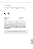
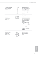
H410M-H/M.2 SE
ATX Power Connector
(24-pin ATXPWR1)
(see p.6, No. 5)
°is motherboard pro-
vides a 24-pin ATX power
connector. To use a 20-
pin ATX power supply,
please plug it along Pin 1
and Pin 13.
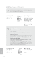
ATX 12V Power
Connector
(8-pin ATX12V1)
(see p.6, No. 1)
°is motherboard
provides a 8-pin ATX 12V
power connector. To use a
4-pin ATX power supply,
please plug it along Pin 1
and Pin 5.
*Warning: Please make
sure that the power cable
connected is for the CPU
and not the graphics
card. Do not plug the
PCIe power cable to this
connector.
Serial Port Header
(9-pin COM1)
(see p.6, No. 17)
°is COM1 header
supports a serial port
module.
4
1
8
5
CCTS#1
RRTS#1
DDSR#1
DDTR#1
RRXD1
GND
TTXD1
DDCD#1
1
RRI#1
12
1
24
13