ASRock H410TM-ITX User Manual - Page 28
M.2_SSD NGFF Module Installation Guide
 |
View all ASRock H410TM-ITX manuals
Add to My Manuals
Save this manual to your list of manuals |
Page 28 highlights
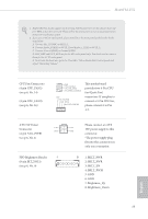
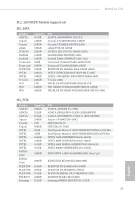
H410TM-ITX 2.7 M.2_SSD (NGFF) Module Installation Guide The M.2, also known as the Next Generation Form Factor (NGFF), is a small size and versatile card edge connector that aims to replace mPCIe and mSATA. The Ultra M.2 Socket supports M Key type 2260/2280 M.2 SATA3 6.0 Gb/s module and M.2 PCI Express module up to Gen3 x4 (32 Gb/s). Installing the M.2_SSD (NGFF) Module Step 1 Prepare a M.2_SSD (NGFF) module and the screw. 2 Step 2 1 Depending on the PCB type and length of your M.2_SSD (NGFF) module, find the corresponding nut location to be used. B A No. Nut Location PCB Length Module Type 1 A 6cm Type2260 2 B 8cm Type 2280 B A Step 3 Remove the screw on the standoff and keep this screw for later use. English 23
-
 1
1 -
2
-
3
-
4
-
5
-
6
-
7
-
8
-
9
-
10
-
11
-
12
-
13
-
14
-
15
-
16
-
17
-
18
-
19
-
20
-
21
-
22
-
 23
23 -
 24
24 -
 25
25 -
 26
26 -
 27
27 -
 28
28 -
 29
29 -
 30
30 -
 31
31 -
 32
32 -
 33
33 -
34
-
35
-
36
-
37
-
38
-
39
-
40
-
41
-
42
-
43
-
44
-
45
-
46
-
47
-
48
-
49
-
50
-
51
-
52
-
53
-
54
-
55
-
56
-
57
-
58
-
59
-
60
-
61
-
62
-
63
-
64
-
65
-
66
-
67
 |
 |
H410TM-ITX
23
English
2.7
M.2_SSD (NGFF) Module Installation Guide
°e M.2, also known as the Next Generation Form Factor (NGFF), is a small size and
versatile card edge connector that aims to replace mPCIe and mSATA.
°e Ultra M.2 Socket supports M Key type 2260/2280 M.2 SATA3 6.0 Gb/s module and M.2
PCI Express module up to Gen3 x4 (32 Gb/s).
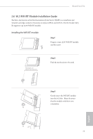
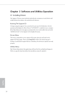
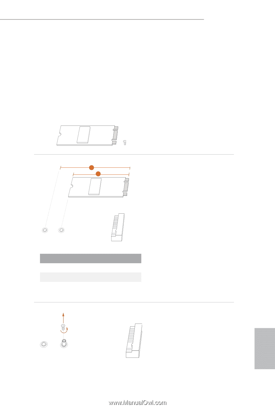
Installing the M.2_SSD (NGFF) Module
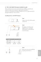
Step 1
Prepare a M.2_SSD (NGFF) module
and the screw.
Step 2
Depending on the PCB type and
length of your M.2_SSD (NGFF)
module, find the corresponding nut
location to be used.
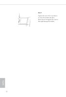
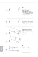
Step 3
Remove the screw on the standoff and
keep this screw for later use.
No.
1
2
Nut Location
A
B
PCB Length
6cm
8cm
Module Type
Type2260
Type 2280
1
2
A
B
B
A