ASRock H470M-STX User Manual
ASRock H470M-STX Manual
 |
View all ASRock H470M-STX manuals
Add to My Manuals
Save this manual to your list of manuals |
ASRock H470M-STX manual content summary:
- ASRock H470M-STX | User Manual - Page 1
- ASRock H470M-STX | User Manual - Page 2
Version 1.0 Published June 2020 This device complies with Part 15 of the FCC Rules. Operation is subject to the following two conditions: (1) this device may not cause harmful interference, and (2) this device must accept any interference received, including interference that may cause undesired - ASRock H470M-STX | User Manual - Page 3
AUSTRALIA ONLY Our goods come with guarantees that cannot be excluded under the Australian Consumer Law. You are entitled to a replacement or refund for a major failure and compensation for any other reasonably foreseeable loss or damage caused by our goods. You are also entitled to have the goods - ASRock H470M-STX | User Manual - Page 4
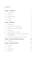
18 2.5 Onboard Headers and Connectors 19 2.6 M.2 WiFi/BT Module and Intel® CNVi (Integrated WiFi/BT) Installation Guide 22 2.7 M.2_SSD (NGFF) Module Installation Guide (M2_1) 24 Chapter 3 Software and Utilities Operation 26 3.1 Installing Drivers 26 Chapter 4 UEFI SETUP UTILITY 27 - ASRock H470M-STX | User Manual - Page 5
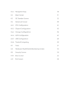
4.3.2 Navigation Keys 30 4.4 Main Screen 31 4.5 OC Tweaker Screen 32 4.6 Advanced Screen 40 4.6.1 CPU Configuration 41 4.6.2 Chipset Configuration 43 4.6.3 Storage Configuration 46 4.6.4 ACPI Configuration 47 4.6.5 USB Configuration 48 4.6.6 Trusted Computing 49 4.7 Tools 51 - ASRock H470M-STX | User Manual - Page 6
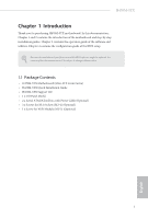
the content of this documentation will be subject to change without notice. 1.1 Package Contents • H470M-STX Motherboard (Mini-STX Form Factor) • H470M-STX Quick Installation Guide • H470M-STX Support CD • 1 x I/O Panel Shield • 2 x Serial ATA(SATA) Data with Power Cable (Optional) • 2 x Screws for - ASRock H470M-STX | User Manual - Page 7
CPU Chipset • Mini-STX Form Factor • Supports 10th Gen Intel® CoreTM Processors (Socket 1200) • Digi Power design • 4 Power Phase design • Supports Intel® Turbo Boost Max 3.0 Technology • Intel® H470 Memory • Dual Channel DDR4 Memory Technology • 2 x DDR4 SO-DIMM Slots • Supports DDR4 2933/2800 - ASRock H470M-STX | User Manual - Page 8
H470M-STX Audio LAN Front Panel I/O • Four graphics output options: D-Sub, HDMI, DisplayPort 1.4 and DisplayPort 1.4 (over USB Type-C Alt Mode) * Supports up to 3 displays simultaneously • Supports HDMI 1.4 with max. resolution up to 4K x 2K (4096x2160) @ 30Hz • Supports D-Sub with max. resolution - ASRock H470M-STX | User Manual - Page 9
CPU and 90W power adapter for 35W CPU. • 1 x D-Sub Port • 1 x HDMI Port • 1 x DisplayPort 1.4 • 4 x USB 3.2 Gen1 Type-A Ports (Supports ESD Protection) • 1 x USB 3.2 Gen1 Type-C Port (Supports ESD Protection) * Supports USB Type-C Alt Mode • 1 x RJ-45 LAN Port with LED (ACT/LINK LED and SPEED LED - ASRock H470M-STX | User Manual - Page 10
H470M-STX OS Certifications • CPU Fan multi-speed control • CASE OPEN detection • Voltage monitoring: +12V, +5V, are not responsible for possible damage caused by overclocking. Mini-STX Chassis Support List Vendor SilverStone Technology Inc. AKasa Model VT01S A-STX04-A1B / A-STX04-M1B English - ASRock H470M-STX | User Manual - Page 11
1.3 Motherboard Layout DC Jack 12 CPU_FAN1 RoHS H470M-STX DDR4_A1 DDR4_B1 VGA1 USB 3.2 Gen1 USB_3 DP_1 HDMI1 USB 3.2 Gen1 T: USB_4 B: USB_5 USB 3.2 Gen1 Top: T: USB_6 B: USB_7 RJ-45 BIOS ROM M2_1_CT1 CPU_FAN2 8 CMOS Battery - ASRock H470M-STX | User Manual - Page 12
Back Side View M2_2 H470M-STX SATA3 SATA3 9 10 7 English - ASRock H470M-STX | User Manual - Page 13
No. Description 1 CPU Fan Connector (CPU_FAN1) 2 2 x 260-pin DDR4 SO-DIMM Slots (DDR4_A1, DDR4_B1) 3 Clear CMOS Jumper (CLRMOS1) 4 System Panel Header (PANEL1) 5 USB 2.0 Header (USB_8_9) 6 MONO Speaker Header (SPEAKER1) 7 Audio Header (AUDIO3) 8 CPU Fan Connector (CPU_FAN2) 9 SATA3 Connector (SATA2) - ASRock H470M-STX | User Manual - Page 14
1.4 Front Panel H470M-STX 1 2 3 4 No. Description 1 Headphone/Headset Jack (AUDIO1) 2 USB 3.2 Gen2 Type-A Port (USB_1) No. Description 3 USB 3.2 Gen1 Type-C Port (USB_2) 4 Microphone Input (AUDIO2) English 9 - ASRock H470M-STX | User Manual - Page 15
19V DC Power Adapters) 2 D-Sub Port 3 USB 3.2 Gen1 Type-C Port (USB_3) (Supports USB Type-C Alt Mode) 4 DisplayPort 1.4 4 6 7 5 No. Description 5 HDMI Port 6 USB 3.2 Gen1 Type-A Ports (USB_4_5) 7 USB 3.2 Gen1 Type-A Ports (USB_6_7) 8 LAN RJ-45 Port** *Specification for - ASRock H470M-STX | User Manual - Page 16
H470M-STX Chapter 2 Installation This is a Mini-STX form factor motherboard. Before you install the motherboard, study the configuration of your chassis to ensure that the motherboard fits into it. Pre-installation Precautions - ASRock H470M-STX | User Manual - Page 17
2.1 Installing the CPU 1. Before you insert the 1200-Pin CPU into the socket, please check if the PnP cap is on the socket, if the CPU surface is unclean, or if there are any bent pins in the socket. Do not force to insert the CPU into the socket if above situation is found. Otherwise, the CPU will - ASRock H470M-STX | User Manual - Page 18
H470M-STX 3 4 5 13 English - ASRock H470M-STX | User Manual - Page 19
Please save and replace the cover if the processor is removed. The cover must be placed if you wish to return the motherboard for after service. 14 English - ASRock H470M-STX | User Manual - Page 20
2.2 Installing the CPU Fan and Heatsink H470M-STX 1 2 CPU_FAN English 15 - ASRock H470M-STX | User Manual - Page 21
2.3 Installing Memory Modules (SO-DIMM) This motherboard provides two 260-pin DDR4 (Double Data Rate 4) SO-DIMM slots. It is not allowed to install a DDR, DDR2 or DDR3 memory module into a DDR4 slot; otherwise, this motherboard and SO-DIMM may be damaged. The SO-DIMM only fits in one correct - ASRock H470M-STX | User Manual - Page 22
H470M-STX 1 2 3 17 English - ASRock H470M-STX | User Manual - Page 23
2.4 Jumpers Setup The illustration shows how jumpers are setup. When the jumper cap is placed on the pins, the jumper is "Short". If no jumper cap is placed on the pins, the jumper is "Open". Clear CMOS Jumper (CLRCMOS1) (see p.6, No. 3) 2-pin Jumper Short: Clear CMOS Open: Default CLRCMOS1 - ASRock H470M-STX | User Manual - Page 24
H470M-STX 2.5 Onboard Headers and Connectors Onboard headers and connectors are NOT jumpers. Do NOT place jumper caps over these headers and connectors. Placing jumper caps over - ASRock H470M-STX | User Manual - Page 25
SATA data cables for internal storage devices with up to 6.0 Gb/s data transfer rate. *The SATA3 connectors support 2.5-inch hard drive (+5V) and do not support 3.5-inch hard drive (+12V) USB 2.0 Header (9-pin USB_8_9) (see p.6, No. 5) USB_PWR P- P+ GND 1 DUMMY GND P+ PUSB_PWR There is one - ASRock H470M-STX | User Manual - Page 26
Audio Header (5-pin AUDIO3) (see p.6, No. 7) H470M-STX 1 Audio-R Audio-L Jack detect GND This Audio header allows you to connect the audio cable for headphone. English 21 - ASRock H470M-STX | User Manual - Page 27
Module and Intel® CNVi (Integrated WiFi/BT) Installation Guide The M.2, also known as the Next Generation Form Factor (NGFF), is a small size and versatile card edge connector that aims to replace mPCIe and mSATA. The M.2 Socket (Key E) supports type 2230 WiFi/BT module and Intel® CNVi (Integrated - ASRock H470M-STX | User Manual - Page 28
A A 20o A H470M-STX Step 3 Gently insert the WiFi/BT module or Intel® CNVi (Integrated WiFi/ BT) into the M.2 slot. Please be aware that the module only fits in - ASRock H470M-STX | User Manual - Page 29
2.7 M.2_SSD (NGFF) Module Installation Guide (M2_1) The M.2, also known as the Next Generation Form Factor (NGFF), is a small size and versatile card edge connector that aims to replace mPCIe and mSATA. The Ultra M.2 Socket supports type 2280 M.2 SATA3 6.0 Gb/s module and M.2 PCI Express module up - ASRock H470M-STX | User Manual - Page 30
H470M-STX M.2_SSD (NGFF) Module Support List Vendor ADATA ADATA Apacer Intel Intel INTEL INTEL INTEL INTEL Kingston PATRIOT PLEXTOR WD BLUE WDS100T1B0B WD Green WDS240G1G0B-00RC30 For the latest updates of M.2_SSD (NFGG) module support list, please visit our website for details. 25 English - ASRock H470M-STX | User Manual - Page 31
CD that comes with the motherboard contains necessary drivers and useful utilities that enhance the motherboard's features. Running The Support CD To begin using the support CD, insert the CD into your CD-ROM drive. The CD automatically displays the Main Menu if "AUTORUN" is enabled in your computer - ASRock H470M-STX | User Manual - Page 32
H470M-STX Chapter 4 UEFI SETUP UTILITY 4.1 Introduction This section explains how to use the UEFI SETUP UTILITY to configure your system. You may run the UEFI SETUP - ASRock H470M-STX | User Manual - Page 33
4.2 EZ Mode The EZ Mode screen appears when you enter the BIOS setup program by default. EZ mode is a dashboard which contains multiple readings of the system's current status. You can check the most crucial information of your system, such as CPU speed, DRAM frequency, SATA information, fan speed, - ASRock H470M-STX | User Manual - Page 34
H470M-STX 4.3 Advanced Mode The Advanced Mode provides more options to configure the BIOS settings. Refer to the following sections for the detailed configurations. To access the - ASRock H470M-STX | User Manual - Page 35
4.3.2 Navigation Keys Use < > key or < > key to choose among the selections on the menu bar, and use < > key or < > key to move the cursor up or down to select items, then press to get into the sub screen. You can also use the mouse to click your required item. Please check the following - ASRock H470M-STX | User Manual - Page 36
H470M-STX 4.4 Main Screen When you enter the UEFI SETUP UTILITY, the Main screen will appear and display the system overview. The availability and location of BIOS - ASRock H470M-STX | User Manual - Page 37
only, and they may not exactly match what you see on your screen. Base Frequency Boost Via ASRock BFB (Boost Frequency Boost) Technology, users may install their non K series CPUs to ASRock's 400 series motherboards (even non Z models) and enjoy the base frequency boost with the hidden power of - ASRock H470M-STX | User Manual - Page 38
H470M-STX BCLK . Intel Thermal Velocity Boost Voltage Optimizations This service controls thermal based voltage optimizations for processors that for CMLS 35W/65W/125W skus.This item is only supported with processors with Config TDP support. Long Duration Power Limit Configure Package Power Limit 1 in - ASRock H470M-STX | User Manual - Page 39
Long Duration Maintained Configure the period of time until the CPU ratio is lowered when the Long Duration Power Limit is exceeded. Short Duration Power Limit Configure Package Power Limit 2 in watts. When the limit is exceeded, the CPU ratio will be lowered immediately. A lower limit can protect - ASRock H470M-STX | User Manual - Page 40
H470M-STX command and opening the next row. RAS# Active Time (tRAS) The number of clock cycles required between a bank active command and issuing the precharge command. - ASRock H470M-STX | User Manual - Page 41
Four Activate Window (tFAW) The time window in which four activates are allowed the same rank. CAS Write Latency (tCWL) Configure CAS Write Latency. Third Timing tREFI Configure refresh cycles at an average periodic interval. tCKE Configure the period of time the DDR4 initiates a minimum of one - ASRock H470M-STX | User Manual - Page 42
latency training. RTL (CH A) Configure round trip latency for channel A. RTL (CH B) Configure round trip latency for channel B. IO-L (CH A) Configure IO latency for channel A. H470M-STX 37 English - ASRock H470M-STX | User Manual - Page 43
to change ODT (CH B) Auto/Manual settings. The default is [Auto]. ODT PARK (A1) Configure the memory on die termination resistors' PARK for channel A. ODT PARK (B1) Configure the memory on die termination resistors' PARK for channel B. Advanced Setting ASRock Timing Optimization Configure the fast - ASRock H470M-STX | User Manual - Page 44
H470M-STX [Enabled] The system will allow performing realtime memory timing changes after MRC_DONE. Command Tristate Configure the Command Tristate Support. Exit On Failure Configure the Exit On Failure for MRC training steps. Reset On Training Fail Reset system if the MRC training fails. MRC Fast - ASRock H470M-STX | User Manual - Page 45
UEFI setup utility. Full HD UEFI When [Auto] is selected, the resolution will be set to 1920 x 1080 if the monitor supports Full HD resolution. If the monitor does not support Full HD resolution, then the resolution will be set to 1024 x 768. When [Disable] is selected, the resolution will be set - ASRock H470M-STX | User Manual - Page 46
H470M-STX Intel Hyper Threading Technology Intel Hyper Threading Technology allows multiple threads to run on each core, so that the overall performance on threaded software is improved. Active Processor Cores Select the number of cores to enable in each processor package. CPU C States Support - ASRock H470M-STX | User Manual - Page 47
sleep state for lower power consumption. Package C State Support Enable CPU, PCIe, Memory, Graphics C State Support for power saving. CFG Lock This item allows Extensions (SGX) Intel SGX is a set of new CPU instructions that can be used by applications to set aside private regions of code and - ASRock H470M-STX | User Manual - Page 48
4.6.2 Chipset Configuration H470M-STX Above 4G Decoding Enable or disable 64bit capable Devices to be decoded in Above 4G Address Space (only if the system supports 64 bit PCI decoding). VT-d Intel® Virtualization Technology for Directed I/O helps your virtual machine monitor better utilize - ASRock H470M-STX | User Manual - Page 49
This option enables/disables the control of ASPM on CPU side of the DMI Link. PCH DMI ASPM Support This option enables/disables the ASPM support for all PCH DMI devices. Share Memory Configure the size of memory that is allocated to the integrated graphics processor when the system boots up. - ASRock H470M-STX | User Manual - Page 50
H470M-STX Restore on AC/Power Loss Select the power state after a power failure. If [Power Off] is selected, the power will remain off when the power recovers. If [Power On] is selected, the system will start to boot up when the power recovers. 45 English - ASRock H470M-STX | User Manual - Page 51
Enable/disable the SATA controllers. SATA Mode Selection AHCI: Supports new features that improve performance. RAID: Combine multiple disk low power state during periods of inactivity to save power. It is only supported by AHCI mode. Hard Disk S.M.A.R.T. S.M.A.R.T stands for Self-Monitoring, Analysis - ASRock H470M-STX | User Manual - Page 52
4.6.4 ACPI Configuration H470M-STX Suspend to RAM Select disable for ACPI suspend type S1. It is recommended to select auto for ACPI S3 power saving. I219 LAN Power On - ASRock H470M-STX | User Manual - Page 53
compatibility issues it is recommended to disable legacy USB support. Select UEFI Setup Only to support USB devices under the UEFI setup and Windows/Linux operating systems only. XHCI Hand-off This is a workaround for OSes without XHCI hand-off support. The XHCI ownership change should be claimed by - ASRock H470M-STX | User Manual - Page 54
4.6.6 Trusted Computing H470M-STX NOTE: Options vary depending on the version of your connected TPM module. Security Device Support Use this item to enable or disable BIOS support for security device. O.S. will not show Security Device. TCG EFI protocol and INT1A interface will not be available. - ASRock H470M-STX | User Manual - Page 55
version 1.3. Device Select Use this item to select the TPM device to be supported. TPM 1.2 will restrict support to TPM 1.2 devices. TPM 2.0 will restrict support to TPM 2.0 devices. Auto will support both with the default set to TPM 2.0 devices. If TPM 2.0 devices are not found, TPM 1.2 devices - ASRock H470M-STX | User Manual - Page 56
4.7 Tools H470M-STX UEFI Tech Service Contact ASRock Tech Service if you are having trouble with your PC. Please setup network configuration before using UEFI Tech Service. Easy RAID Installer Easy RAID Installer helps you to copy the RAID driver from the support CD to your USB storage device. - ASRock H470M-STX | User Manual - Page 57
Internet Flash - DHCP (Auto IP), Auto ASRock Internet Flash downloads and updates the latest UEFI firmware version from our servers for you. Please setup network configuration before using Internet Flash. *For BIOS - ASRock H470M-STX | User Manual - Page 58
H470M-STX 4.8 Hardware Health Event Monitoring Screen This section allows you to monitor the status of the hardware on your system, including the parameters of the CPU - ASRock H470M-STX | User Manual - Page 59
settings in the UEFI Setup Utility. Leave it blank and press enter to remove the password. Secure Boot Use this item to enable or disable support for Secure Boot. Intel(R) Platform Trust Technology Enable/disable Intel PTT in ME. Disable this option to use discrete TPM Module. 54 English - ASRock H470M-STX | User Manual - Page 60
H470M-STX 4.10 Boot Screen This section displays the available devices on your system for you to configure the boot settings and the boot priority. Fast Boot Fast Boot minimizes your computer's boot time. In fast mode you may not boot from an USB storage device. The VBIOS must support UEFI GOP if - ASRock H470M-STX | User Manual - Page 61
If the computer fails to boot for a number of times the system automatically restores the default settings. CSM (Compatibility Support Module) CSM Enable to launch the Compatibility Support Module. Please do not disable unless you're running a WHCK test. Launch PXE OpROM Policy Select UEFI only to - ASRock H470M-STX | User Manual - Page 62
H470M-STX Launch Storage OpROM Policy Select UEFI only to run those that support UEFI option ROM only. Select Legacy only to run those that support legacy option ROM only. Select Do not launch to not execute both legacy and UEFI option ROM. Other PCI Device ROM Priority For PCI devices - ASRock H470M-STX | User Manual - Page 63
4.11 Exit Screen Save Changes and Exit When you select this option the following message, "Save configuration changes and exit setup?" will pop out. Select [OK] to save changes and exit the UEFI SETUP UTILITY. Discard Changes and Exit When you select this option the following message, "Discard - ASRock H470M-STX | User Manual - Page 64
FCC Part 2 Section 2.1077(a) Responsible Party Name: ASRock Incorporation Address: 13848 Magnolia Ave, Chino, CA91710 Phone/Fax No: +1-909-590-8308/+1-909-590-1026 hereby declares that the product Product Name : Motherboard Model Number : H470M-STX Conforms to the following speci cations: FCC Part15 - ASRock H470M-STX | User Manual - Page 65
EU Declaration of Conformity For the following equipment: Motherboard (Product Name) H470M-STX (Model Designation / Trade Name) ڛEMC -Directive 2014/30/EU (from April 20th, 2016) ☐ EN 55022:2010/AC:2011 Class B ڛEN 55024:2010/A1:2015 ڛEN
-
 1
1 -
 2
2 -
 3
3 -
 4
4 -
 5
5 -
 6
6 -
 7
7 -
8
-
9
-
10
-
11
-
12
-
13
-
14
-
15
-
16
-
17
-
18
-
19
-
20
-
21
-
22
-
23
-
24
-
25
-
26
-
27
-
28
-
29
-
30
-
31
-
32
-
33
-
34
-
35
-
36
-
37
-
38
-
39
-
40
-
41
-
42
-
43
-
44
-
45
-
46
-
47
-
48
-
49
-
50
-
51
-
52
-
53
-
54
-
55
-
56
-
57
-
58
-
59
-
60
-
61
-
62
-
63
-
64
-
65
 |
 |