ASRock H470M-STX User Manual - Page 25
Signal Name
 |
View all ASRock H470M-STX manuals
Add to My Manuals
Save this manual to your list of manuals |
Page 25 highlights
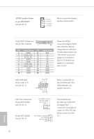
MONO Speaker Header 1 (4-pin SPEAKER1) (see p.6, No. 6) Front_LFront_L+ Front_R+ Front_R- Please connect the chassis speaker to this header. Serial ATA3 Connectors (see p.7, No. 9 and 10) 1 20 PIN Signal Name PIN Signal Name 1 GND 11 2 LVDS_TX+ 12 3 LVDS_TX- 13 4 GND 14 5 GND 15 6 LVDS_RX- 16 7 LVDS_RX+ 17 8 GND 18 9 GND 19 10 GND 20 N/A 5V 5V 5V 5V 5V N/A GND GND GND These two SATA3 connectors support SATA data cables for internal storage devices with up to 6.0 Gb/s data transfer rate. *The SATA3 connectors support 2.5-inch hard drive (+5V) and do not support 3.5-inch hard drive (+12V) USB 2.0 Header (9-pin USB_8_9) (see p.6, No. 5) USB_PWR P- P+ GND 1 DUMMY GND P+ PUSB_PWR There is one header on this motherboard. This USB 2.0 header can support two ports. CPU Fan Connectors (4-pin CPU_FAN1) (see p.6, No. 1) FAN_SPEED_CONTROL CPU_FAN_SPEED FAN_VOLTAGE GND 1 2 34 (4-pin CPU_FAN2) FAN_SPEED_CONTROL 4 (see p.6, No. 8) FAN_SPEED 3 FAN_VOLTAGE 2 GND 1 This motherboard provides two 4-Pin CPU fan (Quiet Fan) connectors. If you plan to connect a 3-Pin CPU fan, please connect it to Pin 1-3. 20 English
-
 1
1 -
2
-
3
-
4
-
5
-
6
-
7
-
8
-
9
-
10
-
11
-
12
-
13
-
14
-
15
-
16
-
17
-
18
-
19
-
 20
20 -
 21
21 -
 22
22 -
 23
23 -
 24
24 -
 25
25 -
 26
26 -
 27
27 -
 28
28 -
 29
29 -
 30
30 -
31
-
32
-
33
-
34
-
35
-
36
-
37
-
38
-
39
-
40
-
41
-
42
-
43
-
44
-
45
-
46
-
47
-
48
-
49
-
50
-
51
-
52
-
53
-
54
-
55
-
56
-
57
-
58
-
59
-
60
-
61
-
62
-
63
-
64
-
65
 |
 |
