ASRock H510 Pro BTC User Manual - Page 26
Important: Make sure
 |
View all ASRock H510 Pro BTC manuals
Add to My Manuals
Save this manual to your list of manuals |
Page 26 highlights
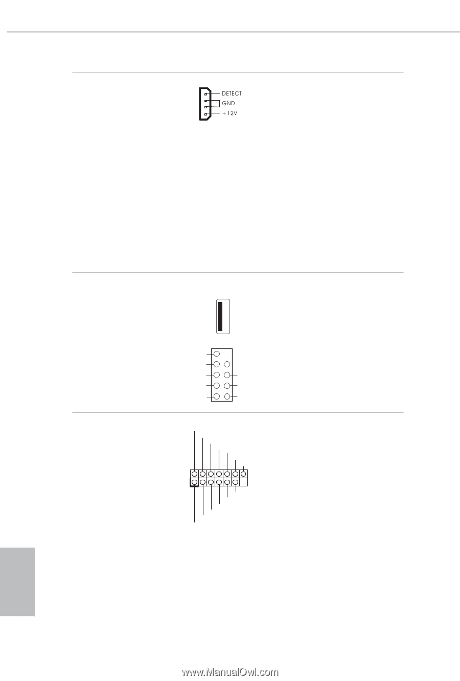
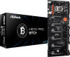
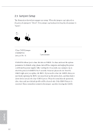
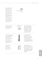
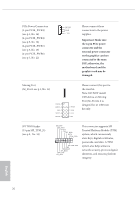
PCIe Power Connectors (4-pin PCIE_PWR3) (see p.5, No. 16) (4-pin PCIE_PWR4) (see p.5, No. 18) (4-pin PCIE_PWR5) (see p.5, No. 19) (4-pin PCIE_PWR6) (see p.5, No. 22) Please connect these connectors to the power supplies. Important: Make sure the 4-pin PCIe power connector and the external power connector on the graphics card are connected to the same PSU; otherwise, the motherboard and the graphics card may be damaged. Mining Port (M_Port1: see p.5, No. 15) 9 PERXN PERXP 8 GND 7 PETXP 6 PETXN 5 1 WAKE# 2 CLKN 3 CLKP 4 RST Please connect this port to the riser kit. Note: DO NOT install USB device on Mining Port (M_Port1), it is designed for x1 USB riser kit only. SPI TPM Header (13-pin SPI_TPM_J1) (see p.5, No. 14) SPI_DQ3 SPI_PWR Dummy CLK SPI_MOSI RST# TPM_PIRQ 1 SPI_TPM_CS# GND RSMRST# SPI_MISO SPI_CS0 SPI_DQ2 This connector supports SPI Trusted Platform Module (TPM) system, which can securely store keys, digital certificates, passwords, and data. A TPM system also helps enhance network security, protects digital identities, and ensures platform integrity. English 20
-
 1
1 -
2
-
3
-
4
-
5
-
6
-
7
-
8
-
9
-
10
-
11
-
12
-
13
-
14
-
15
-
16
-
17
-
18
-
19
-
20
-
 21
21 -
 22
22 -
 23
23 -
 24
24 -
 25
25 -
 26
26 -
 27
27 -
 28
28 -
 29
29 -
 30
30 -
 31
31 -
32
-
33
-
34
-
35
-
36
-
37
-
38
-
39
-
40
-
41
-
42
-
43
-
44
-
45
-
46
-
47
-
48
-
49
-
50
-
51
-
52
-
53
-
54
-
55
-
56
-
57
-
58
-
59
-
60
-
61
-
62
-
63
-
64
-
65
-
66
-
67
-
68
-
69
-
70
 |
 |