ASRock H61M-DGS User Manual - Page 24
Onboard Headers and Connectors
 |
View all ASRock H61M-DGS manuals
Add to My Manuals
Save this manual to your list of manuals |
Page 24 highlights
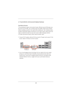
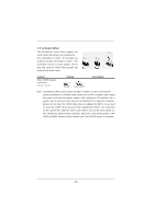
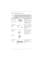
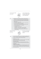
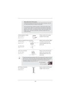
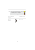
2.9 Onboard Headers and Connectors Onboard headers and connectors are NOT jumpers. Do NOT place jumper caps over these headers and connectors. Placing jumper caps over the headers and connectors will cause permanent damage of the motherboard! Serial ATAII Connectors (SATA2_0: see p.12, No. 10) (SATA2_1: see p.12, No. 8) (SATA2_2: see p.12, No. 12) (SATA2_3: see p.12, No. 11) SATA2_3 SATA2_1 SATA2_2 SATA2_0 These four Serial ATAII (SATAII) connectors support SATA data cables for internal storage devices. The current SATAII interface allows up to 3.0 Gb/s data transfer rate. Serial ATA (SATA) Data Cable (Optional) Either end of the SATA data cable can be connected to the SATA / SATAII hard disk or the SATAII connector on this motherboard. USB 2.0 Headers (9-pin USB6_7) (see p.12 No. 15) (9-pin USB8_9) (see p.12 No. 16) USB_PWR P-9 P+9 GND DUMMY 1 GND P+8 P-8 USB_PWR Besides six default USB 2.0 ports on the I/O panel, there are two USB 2.0 headers on this motherboard. Each USB 2.0 header can support two USB 2.0 ports. Print Port Header (25-pin LPT1) (see p.12 No. 18) AFD# ERROR# PINIT# SLIN# GND 1 SPD7 SPD6 ACK# SPD5 BUSY SPD4 PE SPD3 SLCT SPD2 SPD1 SPD0 STB# This is an interface for print port cable that allows convenient connection of printer devices. 24
-
 1
1 -
2
-
3
-
4
-
5
-
6
-
7
-
8
-
9
-
10
-
11
-
12
-
13
-
14
-
15
-
16
-
17
-
18
-
 19
19 -
 20
20 -
 21
21 -
 22
22 -
 23
23 -
 24
24 -
 25
25 -
 26
26 -
 27
27 -
 28
28 -
 29
29 -
30
-
31
-
32
-
33
-
34
-
35
-
36
-
37
-
38
-
39
-
40
-
41
-
42
-
43
-
44
-
45
-
46
-
47
-
48
-
49
-
50
-
51
-
52
-
53
 |
 |
