ASRock H91M-S1 PLUS User Manual - Page 23
Hese two SA´A2 - motherboard manual
 |
View all ASRock H91M-S1 PLUS manuals
Add to My Manuals
Save this manual to your list of manuals |
Page 23 highlights
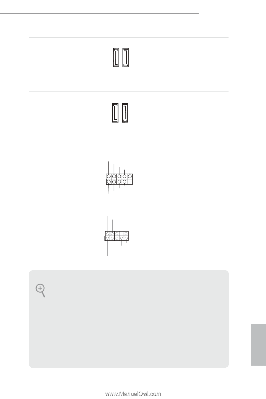
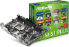
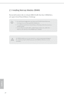
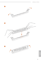
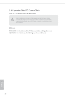
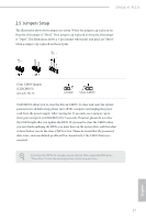
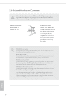
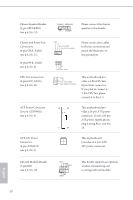
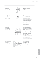
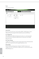
H91M-S1 PLUS Serial ATA2 Connectors (SATA_2: see p.6, No. 6) (SATA_3: see p.6, No. 5) SATA_3 SATA_2 hese two SATA2 connectors support SATA data cables for internal storage devices with up to 3.0 Gb/s data transfer rate. Serial ATA3 Connectors (SATA_0: see p.6, No. 7) (SATA_1: see p.6, No. 8) SATA_1 SATA_0 hese two SATA3 connectors support SATA data cables for internal storage devices with up to 6.0 Gb/s data transfer rate. USB 2.0 Headers (9-pin USB4_5) (see p.6, No. 14) (9-pin USB6_7) (see p.6, No. 13) USB_PWR P-7 P+7 GND DUMMY 1 GND P+6 P-6 USB_PWR Besides four USB 2.0 ports on the I/O panel, there are two headers on this motherboard. Each USB 2.0 header can support two ports. Front Panel Audio Header (9-pin HD_AUDIO1) (see p.6, No. 20) GND PRESENCE# MIC_RET OUT_RET 1 OUT2_L J_SENSE OUT2_R MIC2_R MIC2_L his header is for connecting audio devices to the front audio panel. 1. High Deinition Audio supports Jack Sensing, but the panel wire on the chassis must support HDA to function correctly. Please follow the instructions in our manual and chassis manual to install your system. 2. If you use an AC'97 audio panel, please install it to the front panel audio header by the steps below: A. Connect Mic_IN (MIC) to MIC2_L. B. Connect Audio_R (RIN) to OUT2_R and Audio_L (LIN) to OUT2_L. C. Connect Ground (GND) to Ground (GND). D. MIC_RET and OUT_RET are for the HD audio panel only. You don't need to connect them for the AC'97 audio panel. E. To activate the front mic, go to the "FrontMic" Tab in the Realtek Control panel and adjust "Recording Volume". 19 English
-
 1
1 -
2
-
3
-
4
-
5
-
6
-
7
-
8
-
9
-
10
-
11
-
12
-
13
-
14
-
15
-
16
-
17
-
 18
18 -
 19
19 -
 20
20 -
 21
21 -
 22
22 -
 23
23 -
 24
24 -
 25
25 -
 26
26 -
 27
27 -
 28
28 -
29
-
30
-
31
-
32
-
33
-
34
-
35
-
36
-
37
-
38
-
39
-
40
-
41
-
42
-
43
-
44
-
45
-
46
-
47
-
48
-
49
-
50
-
51
-
52
-
53
-
54
-
55
-
56
-
57
-
58
-
59
-
60
-
61
-
62
-
63
-
64
-
65
-
66
-
67
-
68
-
69
-
70
-
71
-
72
-
73
-
74
-
75
-
76
-
77
-
78
-
79
-
80
-
81
-
82
-
83
-
84
-
85
 |
 |