ASRock K7S8X R3.0 User Manual - Page 15
Connectors
 |
View all ASRock K7S8X R3.0 manuals
Add to My Manuals
Save this manual to your list of manuals |
Page 15 highlights
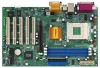
CLRCMOS2 (see p.7/p.8 item 15) Clear CMOS 2-pin jumper Note: CLRCMOS2 allows you to clear the data in CMOS. The data in CMOS includes system setup information such as system password, date, time, and system setup parameters. To clear and reset the system parameters to default setup, please turn off the computer and unplug the power cord, then use a jumper cap to short the pins on CLRCMOS2 for 3 seconds. Please remember to remove the jumper cap after clearing the CMOS. 2.8 Connectors Connectors are NOT jumpers. DO NOT place jumper caps over these connectors. Connector Figure Description FDD connector (33-pin FLOPPY1) (see p.7/p.8 item 14) Pin1 FLOPPY1 Red marking Note: Match the red marking on the floppy ribbon cable with Pin1. Primary IDE connector (Blue) (39-pin IDE1, see p.7/p.8 item 8) Secondary IDE connector (Black) (39-pin IDE2, see p.7/p.8 item 7) PIN1 IDE1 PIN1 IDE2 connect the blue end to the motherboard connect the black end to the IDE devices 80-Pin ATA 100/133 cable Note: To optimize compatibility and performance, please connect your hard disk drive to the primary IDE connector (IDE1, blue) and CD-ROM to the secondary IDE connector (IDE2, black). 15
-
 1
1 -
2
-
3
-
4
-
5
-
6
-
7
-
8
-
9
-
 10
10 -
 11
11 -
 12
12 -
 13
13 -
 14
14 -
 15
15 -
 16
16 -
 17
17 -
 18
18 -
 19
19 -
 20
20 -
21
-
22
-
23
-
24
-
25
-
26
-
27
-
28
-
29
 |
 |
