ASRock K7S8X R3.0 User Manual - Page 16
CD-ROM, DVD-ROM, TV
 |
View all ASRock K7S8X R3.0 manuals
Add to My Manuals
Save this manual to your list of manuals |
Page 16 highlights
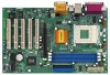
USB 2.0 header (9-pin USB45) (see p.7/p.8 item 19) Infrared module connector (5-pin IR1) (see p.7/p.8 item 18) Internal audio connectors (4-pin CD1, 4-pin AUX1) (CD1: see p.7/p.8 item 28) (AUX1: see p.7/p.8 item 27) Front panel audio connector (9-pin AUDIO1) (see p.7/p.8 item 26) System panel connector (9-pin PANEL1) (see p.7/p.8 item 16) External speaker connector (4-pin SPEAKER 1) (see p.7/p.8 item 17) Chassis fan connector (3-pin CHA_FAN1) (see p.7/p.8 item 13) CPU fan connector (3-pin CPU_FAN1) (see p.7/p.8 item 2) ATX power connector (20-pin ATXPWR1) (see p.7/p.8 item 6) USB_PWR P-5 P+5 GND DUMMY 1 GND P+4 P-4 USB_PWR IRTX +5V DUMMY 1 GND IRRX CD-L GND GND CD-R AUX-L GND GND AUX-R CD1 AUX1 GND +5VA BACKOUT-R BACKOUT-L 1 A U D - O U T- L DUMMY A U D - O U T- R MIC-POWER MIC PLED+ PLEDPWRBTN# GND 1 DUMMY RESET# GND HDLEDHDLED+ 1 SPEAKER DUMMY DUMMY +5V GND +12V CHA_FAN_SPEED CPU_FAN_SPEED +12V GND ASRock I/OTM provides 4 default USB 2.0 ports on the rear panel. If those 4 USB 2.0 ports on the rear panel are not sufficient, this USB 2.0 header is available for 2 additional USB 2.0 ports. This connector supports an optional wireless transmitting and receiving infrared module. These connectors allow you to receive stereo audio input from sound sources such as a CD-ROM, DVD-ROM, TV tuner card, or MPEG card. This is an interface for front panel audio cable that allows convenient connection and control of audio devices. This connector accommodates several system front panel functions. This connector allows you to attach to an external speaker. Connect the fan cable to the connector matching the black wire to the ground pin. Connect the fan cable to the connector matching the black wire to the ground pin. Connect an ATX power supply to the connector. 16
-
 1
1 -
2
-
3
-
4
-
5
-
6
-
7
-
8
-
9
-
10
-
 11
11 -
 12
12 -
 13
13 -
 14
14 -
 15
15 -
 16
16 -
 17
17 -
 18
18 -
 19
19 -
 20
20 -
 21
21 -
22
-
23
-
24
-
25
-
26
-
27
-
28
-
29
 |
 |
