ASRock M3A780GXH/128M User Manual
ASRock M3A780GXH/128M Manual
 |
View all ASRock M3A780GXH/128M manuals
Add to My Manuals
Save this manual to your list of manuals |
ASRock M3A780GXH/128M manual content summary:
- ASRock M3A780GXH/128M | User Manual - Page 1
M3A780GXH/128M User Manual Version 1.0 Published April 2009 Copyright©2009 ASRock INC. All rights reserved. 1 - ASRock M3A780GXH/128M | User Manual - Page 2
purchaser for backup purpose, without written consent of ASRock Inc. Products and corporate names appearing in this manual may or may not be registered trademarks or copyrights USA ONLY The Lithium battery adopted on this motherboard contains Perchlorate, a toxic substance controlled in Perchlorate - ASRock M3A780GXH/128M | User Manual - Page 3
-DVD Playback Support 12 1.6 1080p Blu-ray (BD) / HD-DVD Films Which Pass Our Lab Test . 13 1.7 Motherboard Layout 14 Guide ....... 47 2.16 Driver Installation Guide 49 2.17 Installing Windows® XP / XP 64-bit / VistaTM / VistaTM 64-bit With RAID Functions 49 2.17.1 Installing Windows® XP / XP 64 - ASRock M3A780GXH/128M | User Manual - Page 4
/ VistaTM 64-bit Without RAID Functions 52 2.19 Untied Overclocking Technology 53 3 . BIOS SETUP UTILITY 54 3.1 Introduction 54 3.1.1 BIOS Menu Bar 4 . Software Support 77 4.1 Install Operating System 77 4.2 Support CD Information 77 4.2.1 Running Support CD 77 4.2.2 Drivers Menu 77 4.2.3 - ASRock M3A780GXH/128M | User Manual - Page 5
about the model you are using. www.asrock.com/support/index.asp 1.1 Package Contents 1 x ASRock M3A780GXH/128M Motherboard (ATX Form Factor: 12.0-in x 8.8-in, 30.5 cm x 22.4 cm) 1 x ASRock M3A780GXH/128M Quick Installation Guide 2 x ASRock M3A780GXH/128M Support CD 1 x Ultra ATA 66/100/133 IDE - ASRock M3A780GXH/128M | User Manual - Page 6
Platform CPU Chipset Memory Expansion Slot Graphics Audio LAN - ATX Form Factor: 12.0-in x 8.8-in, 30.5 cm x 22.4 cm - All Solid Capacitor design (100% Japan-made high-quality Conductive Polymer Capacitors) - Support for Socket AM3 processors: AMD PhenomTM II X4 / X3 (except 920 / 940) and Athlon - ASRock M3A780GXH/128M | User Manual - Page 7
- 8Mb AMI BIOS - AMI Legal BIOS - Supports "Plug and Play" - ACPI 1.1 Compliance Wake Up Events - Supports jumperfree - SMBIOS 2.3.1 Support - CPU, VCCM, NB, SB Voltage Multi-adjustment - Supports Smart BIOS - Drivers, Utilities, AntiVirus Software (Trial Version), AMD OverDriveTM Utility, AMD Live - ASRock M3A780GXH/128M | User Manual - Page 8
. 3. Whether 1600MHz memory speed is supported depends on the AM3 CPU you adopt. If you want to adopt DDR3 1600 memory module on this motherboard, please refer to the memory support list on our website for the compatible memory modules. ASRock website http://www.asrock.com 4. Due to the operating - ASRock M3A780GXH/128M | User Manual - Page 9
reverse the direction of ASRock SLI/XFire Switch Card in advance. 6. The maximum shared memory size is defined by the chipset vendor and is subject to change. Please check AMD website for the latest information. 7. 1080p Blu-ray (BD) / HD-DVD playback support on this motherboard requires the proper - ASRock M3A780GXH/128M | User Manual - Page 10
15. While CPU overheat is detected, the system will automatically shutdown. Before you resume the system, please check if the CPU fan on the motherboard functions properly and unplug the power cord, then plug it back again. To improve heat dissipation, remember to spray thermal grease between the - ASRock M3A780GXH/128M | User Manual - Page 11
website: http://www.asrock.com/support/index.htm 1.4 Three CrossFireXTM Graphics Card Support List (for Windows® VistaTM / VistaTM 64-bit) Chipset Vendor ATI Model Name Gecube GC-HD485PG3-E3 Powercolor AX4870 512MD5-H Chipset Name RADEON 4850 RADEON 4870 Driver Catalyst 8.12 + Hotfix Catalyst - ASRock M3A780GXH/128M | User Manual - Page 12
DVD playback is only supported under Windows® VistaTM / VistaTM 64-bit OS. If you install Windows® XP / XP 64-bit OS, the function of 1080p Blu-ray (BD) / HD-DVD playback is not available, please visit our website for AMD 780G VGA driver update in the future. ASRock website http://www.asrock.com 12 - ASRock M3A780GXH/128M | User Manual - Page 13
* MPEG-4-AVC mentioned above refers to the same format of H.264. * Above passed films are tested under below configuration. Items Configurations CPU AM3 all series CPU VGA Onboard VGA with DVI-D port Memory Single Channel DDR3 1066, 1GB x 1 OS Windows® VistaTM or Windows® VistaTM - ASRock M3A780GXH/128M | User Manual - Page 14
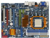
CTR BASS MIC IN Top: LINE IN Center: Bottom: PWR_FAN1 PCIE1 LAN PHY Hybrid CrossFire CrossFireX Sideport memory 128MB AMD 780G Chipset RAID NB_FAN1 M3A780GXH/128M PCIE2 IDE1 Super I/O AUDIO CODEC HDMI_SPDIF1 1 CD1 HD_AUDIO1 1 PCIE3 PCI1 PCI Express 2.0 PCIE4 COM1 1 PCI2 FLOPPY1 CMOS - ASRock M3A780GXH/128M | User Manual - Page 15
(No. 6) (No. 7) (No. 5) 2 V -- -- -- 4 V V -- -- 6 V V V -- 8 V V V V *** To support AC3 audio format with HDMI Audio under VistaTM, please install the HDMI audio driver in XP support CD AAX780GX-10. The driver is located under the path: ..\Drivers\NB Audio\REALTEK\XP64_XP(R1 - ASRock M3A780GXH/128M | User Manual - Page 16
2. Installation This is an ATX form factor (12.0-in x 8.8-in, 30.5 cm x 22.4 cm) motherboard. Before you install the motherboard, study the configuration of your chassis to ensure that the motherboard fits into it. Pre-installation Precautions Take note of the following precautions before you - ASRock M3A780GXH/128M | User Manual - Page 17
Socket Lever 2.2 Installation of CPU Fan and Heatsink After you install the CPU into this motherboard, it is necessary to install a larger heatsink and cooling fan to dissipate heat. You 3). For proper installation, please kindly refer to the instruction manuals of the CPU fan and the heatsink. 17 - ASRock M3A780GXH/128M | User Manual - Page 18
2.3 Installation of Memory Modules (DIMM) This motherboard provides four 240-pin DDR3 (Double Data Rate 3) DIMM slots, and supports Dual Channel Memory Technology. For dual channel configuration, you always need to install identical (the same brand, speed, size and chip-type) DDR3 DIMM pair - ASRock M3A780GXH/128M | User Manual - Page 19
matches the break on the slot. notch break notch break The DIMM only fits in one correct orientation. It will cause permanent damage to the motherboard and the DIMM if you force the DIMM into the slot at incorrect orientation. Step 3. Firmly insert the DIMM into the slot until the retaining - ASRock M3A780GXH/128M | User Manual - Page 20
slots on this motherboard. PCI Slots: support CrossFireXTM function. PCIE3 (PCIE x16 slot; Blue) is used to install PCI Express graphics cards to support to install PCI Express graphics cards to support 3-Way CrossFireXTM function. PCIE1 slot (x1 this motherboard, please install it on PCIE2 slot - ASRock M3A780GXH/128M | User Manual - Page 21
bandwidth. 3. In 3-Way CrossFireXTM mode, please reverse the direction of ASRock SLI/XFire Switch Card, and install PCI Express x16 graphics cards on the installation. Step 2. Remove the system unit cover (if your motherboard is already installed in a chassis). Step 3. Remove the bracket facing - ASRock M3A780GXH/128M | User Manual - Page 22
your system boots. If you haven't installed onboard VGA driver yet, please install onboard VGA driver from our support CD to your system and restart your computer. Then you can start to use dual monitor function on this motherboard. 1. DVI-D and HDMI ports cannot function at the same time. When one - ASRock M3A780GXH/128M | User Manual - Page 23
memory. If you do not adjust the BIOS setup, the default value of "Share Memory", [Auto], will disable VGA/D-Sub function when the add-on VGA card is inserted to this motherboard. 5. Install the onboard VGA driver and the add-on PCI Express VGA card driver to your system. If you have installed - ASRock M3A780GXH/128M | User Manual - Page 24
/ VistaTM 64-bit OS: supported on this motherboard. To use HDCP function with this motherboard, you need to adopt the monitor that supports HDCP function as well. Therefore, you can enjoy the superior display quality with high-definition HDCP encryption contents. Please refer to below instruction - ASRock M3A780GXH/128M | User Manual - Page 25
has released or will release in the future, please refer to ATITM graphics card manuals for detailed installation guide. Step 1. There is one ASRock SLI/XFire Switch Card factory-mounted on this motherboard. This card served as a switch between the default mode (x16) and CrossFireXTM mode (x8 - ASRock M3A780GXH/128M | User Manual - Page 26
Step 2. To change it to CrossFireXTM mode, you need to reverse the direction of ASRock SLI/XFire Switch Card. Please simultaneously pull open both the retention arms that hold the card in position. The card itself will spring away from - ASRock M3A780GXH/128M | User Manual - Page 27
(CrossFireTM Bridge is provided with the graphics card you purchase, not bundled with this motherboard. Please refer to your graphics card vendor for details.) CrossFireTM Bridge Step 8. Connect to the DVI to D-Sub adapter.) Step 9. Connect a 4-pin ATX power cable to SLI/XFIRE power connector. 27 - ASRock M3A780GXH/128M | User Manual - Page 28
Step 2. Follow step 1 to 4 on page 25 and 26 to reverse the direction of ASRock SLI/XFire Switch Card. Install one Radeon graphics card to PCIE2 slot. For the proper the graphics card you purchase, not bundled with this motherboard. Please refer to your graphics card vendor for details.) 28 - ASRock M3A780GXH/128M | User Manual - Page 29
adapter to convert the DVI connector to D-Sub interface, and then connect the D-Sub monitor cable to the DVI to D-Sub adapter.) Step 7. Connect a 4-pin ATX power cable to SLI/XFIRE power connector. 29 - ASRock M3A780GXH/128M | User Manual - Page 30
utility to uninstall any previously installed Catalyst drivers prior to installation. Please check AMD website for ATITM driver updates. Step 3. Step 4. Step 5. Install the required drivers to your system. For Windows® XP OS: A. ATITM recommends Windows® XP Service Pack 2 or higher to be installed - ASRock M3A780GXH/128M | User Manual - Page 31
is used only for identification or explanation and to the owners' benefit, without intent to infringe. * For further information of ATITM CrossFireXTM technology, please check AMD website for updates and details. 31 - ASRock M3A780GXH/128M | User Manual - Page 32
2.7 Hybrid CrossFireXTM Operation Guide This motherboard supports ATITM Hybrid CrossFireXTM feature. ATITM Hybrid CrossFireXTM brings multi-GPU performance capabilities by enabling an AMD 780G integrated graphics processor and a discrete graphics processor to operate simultaneously with combined - ASRock M3A780GXH/128M | User Manual - Page 33
used only for identification or explanation and to the owners' benefit, without intent to infringe. * For further information of ATITM Hybrid CrossFireXTM technology, please check AMD website for up dates and details. 33 - ASRock M3A780GXH/128M | User Manual - Page 34
and pin3 on CLRCMOS1 for 5 seconds. However, please do not clear the CMOS right after you update the BIOS. If you need to clear the CMOS when you just finish updating the BIOS, you must boot up the system first, and then shut it down before you do the clear-CMOS action - ASRock M3A780GXH/128M | User Manual - Page 35
to the motherboard connect the black end to the IDE devices 80-conductor ATA 66/100/133 cable Note: Please refer to the instruction of your p.14, No. 23) SATAII_6 These six Serial ATAII (SATAII) connectors support SATAII or SATA hard disk for internal SATAII_1 SATAII_2 storage devices. The - ASRock M3A780GXH/128M | User Manual - Page 36
supply. Besides six default USB 2.0 ports on the I/O panel, there are three USB 2.0 headers on this motherboard. Each USB 2.0 header can support two USB 2.0 ports. This header supports an optional wireless transmitting and receiving infrared module. This connector allows you to receive stereo audio - ASRock M3A780GXH/128M | User Manual - Page 37
supports Jack Sensing, but the panel wire on the chassis must support HDA to function correctly. Please follow the instruction in our manual and chassis manual 97 audio panel. E. Enter BIOS Setup Utility. Enter Advanced the front mic. For Windows® XP / XP 64-bit OS: Please select "Front Mic" as - ASRock M3A780GXH/128M | User Manual - Page 38
(Quiet Fan) support, the 3-Pin CPU fan still can work successfully even without the fan speed control function. If you plan to connect the 3-Pin CPU fan to the CPU fan connector on this motherboard, please connect it to Pin 1-3. Pin 1-3 Connected 3-Pin Fan Installation ATX Power Connector (24 - ASRock M3A780GXH/128M | User Manual - Page 39
one IEEE 1394 header (FRONT_1394) on this motherboard. This IEEE 1394 header can support one IEEE 1394 port. This COM1 header supports a serial port module. HDMI_SPDIF header, providing SPDIF audio output to HDMI VGA card, allows the system to connect HDMI Digital TV/ projector/LCD devices. Please - ASRock M3A780GXH/128M | User Manual - Page 40
) C B A Please connect the black end (A) of HDMI_SPDIF cable to the HDMI_SPDIF header on the motherboard. Then connect the white end (B or C) of HDMI_SPDIF cable to the HDMI_SPDIF connector of HDMI VGA card. A. black end +5V SPDIFOUT GND blue black B. white end (2-pin) SPDIFOUT GND blue - ASRock M3A780GXH/128M | User Manual - Page 41
refer to page 39. For the pin definition of HDMI_SPDIF connectors on HDMI VGA card, please refer to the user manual of HDMI VGA card vendor. Incorrect connection may cause permanent damage to this motherboard and the HDMI VGA card. Step 3. Connect the white end (B or C) of HDMI_SPDIF cable to - ASRock M3A780GXH/128M | User Manual - Page 42
guide. Some default setting of SATAII hard disks may not be at SATAII mode, which operate with the best performance. In order to enable SATAII function, please follow the below instruction 's website for details: http://www.hitachigst.com/hdd/support/download.htm The above examples are just for your - ASRock M3A780GXH/128M | User Manual - Page 43
eSATAII Interface Introduction What is eSATAII? This motherboard supports eSATAII interface, the external SATAII specification. . 2. If you set "SATA Operation Mode" option in BIOS setup to IDE mode, Hot Plug function is not supported with eSATAII devices. If you still want to use eSATAII function - ASRock M3A780GXH/128M | User Manual - Page 44
How to install eSATAII? SATAII_6 eSATAII_TOP 1. In order to enable the eSATAII port of the I/O shield, you need to connect the orange SATAII connector (SATAII_6; see p.14 No.23) and the eSATAII connector (eSATAII_TOP; see p.14 No.42) with a SATA data cable first. Connect the Connect the SATA - ASRock M3A780GXH/128M | User Manual - Page 45
Comparison between eSATAII and other devices IEEE 1394 USB 2.0 SATA eSATAII/SATAII 400Mb/s 480Mb/s 1.5Gb/s (1500Mb/s) 3.0Gb/s (3000Mb/s) 45 - ASRock M3A780GXH/128M | User Manual - Page 46
This motherboard adopts AMD SB710 south bridge chipset that supports Serial ATA (SATA) / Serial ATAII (SATAII) hard disks and RAID (RAID 0, RAID 1, RAID 10 and JBOD) functions. You may install SATA / SATAII hard disks on this motherboard for internal storage devices. This section will guide you - ASRock M3A780GXH/128M | User Manual - Page 47
is installed into system properly. The latest SATA / SATAII driver is available on our support website: www.asrock.com 4. Make sure to use the SATA power cable & data cable, which are from our motherboard package. 5. Please follow below instructions step by step to reduce the risk of HDD crash or - ASRock M3A780GXH/128M | User Manual - Page 48
cable to (White) to the power supply 1x4-pin cable. the motherboard's SATAII connector. SATA power cable 1x4-pin power connector (White) Step attention, before you process the Hot Unplug: Please do follow below instruction sequence to process the Hot Unplug, improper procedure will cause the SATA - ASRock M3A780GXH/128M | User Manual - Page 49
to [RAID]. STEP 2: Make a SATA / SATAII Driver Diskette. A. Insert the ASRock Support CD into your optical drive to boot your system. (There are two ASRock Support CD in the motherboard gift box pack, please choose the one for Windows® XP / XP 64-bit.) B. During POST at the beginning of - ASRock M3A780GXH/128M | User Manual - Page 50
the left on the bottom to load the AMD RAID drivers. AMD RAID drivers are in the following path in our Support CD: (There are two ASRock Support CD in the motherboard gift box pack, please choose the one for Windows® VistaTM / VistaTM 64-bit.) .. \ I386 (For Windows® VistaTM OS) .. \ AMD64 (For - ASRock M3A780GXH/128M | User Manual - Page 51
"SATA Operation Mode" to [RAID] in BIOS first. Then, please set the RAID configuration by using the Windows RAID installation guide in the following path in the Support CD: .. \ RAID Installation Guide NOTE2. Currently, if you install Windows® VistaTM / Windows® VistaTM 64-bit on IDE HDDs and there - ASRock M3A780GXH/128M | User Manual - Page 52
the left on the bottom to load the AMD AHCI drivers. AMD AHCI drivers are in the following path in our Support CD: (There are two ASRock Support CD in the motherboard gift box pack, please choose the one for Windows® VistaTM / VistaTM 64-bit.) .. \ I386 (For Windows® VistaTM OS) .. \ AMD64 (For - ASRock M3A780GXH/128M | User Manual - Page 53
19 Untied Overclocking Technology This motherboard supports Untied Overclocking Technology, which means during overclocking, FSB enjoys better margin due to fixed PCI / PCIE buses. Before you enable Untied Overclocking function, please enter "Overclock Mode" option of BIOS setup to set the selection - ASRock M3A780GXH/128M | User Manual - Page 54
SETUP UTILITY 3.1 Introduction This section explains how to use the BIOS SETUP UTILITY to configure your system. The SPI Memory on the motherboard stores the BIOS SETUP UTILITY. You may run the BIOS SETUP UTILITY when you start up the computer. Please press during the Power-On-Self-Test (POST - ASRock M3A780GXH/128M | User Manual - Page 55
Advanced H/W Monitor Boot Security Exit System Overview System Time System Date [17:00:09] [Wed 04/08/2009] BIOS Version : M3A780GXH/128M P1.0 Processor Type : AMD Engineering Sample (64bit) Processor Speed : 2500MHz Microcode Update : 100F41/1000086 L1 Cache Size : 512KB L2 Cache Size : 2048KB - ASRock M3A780GXH/128M | User Manual - Page 56
changes and exit setup?" Select [OK] to save the changes and exit the BIOS SETUP UTILITY. Load BIOS Defaults Load BIOS default values for all the setup questions. F9 key can be used for this overclocing may cause damage to your CPU and motherboard. It should be done at your own risk and expense. 56 - ASRock M3A780GXH/128M | User Manual - Page 57
section may cause the system to malfunction. 3.4.1 CPU Configuration BIOS SETUP UTILITY Advanced CPU Configuration Overclock Mode CPU Frequency (MHz) multiplier and voltage will be left at the rated frequency/voltage. If Manual, multiplier and voltage will be set based on User Selection in Setup - ASRock M3A780GXH/128M | User Manual - Page 58
AMD-V. The default value is [Enabled]. Configuration options: [Enabled] and [Disabled]. Enhance Halt State All processors support the Halt State (C1). The C1 state is supported through the native processor instructions by default. If it is set to [Manual], you may adjust the value of Processor - ASRock M3A780GXH/128M | User Manual - Page 59
BIOS SETUP UTILITY Advanced CPU Configuration Overclock Mode CPU Frequency (MHz) PCIE Frequency (MHz) x5.0 1000 MHz] If AUTO, multiplier and voltage will be left at the rated frequency/voltage. If Manual, multiplier and voltage will be set based on User Selection in Setup. +F1 F9 F10 ESC Select - ASRock M3A780GXH/128M | User Manual - Page 60
3.4.2 Memory Configuration BIOS SETUP UTILITY Advanced Memory Configuration Memory Clock Flexibility Option Memory Controller Mode Bank Interleaving Power Down Enable Channel Interleaving Timing : 4-4-4-12 CAS Latency (CL) TRCD - ASRock M3A780GXH/128M | User Manual - Page 61
TRP Use this to adjust TRP values. Configuration options: [Auto], [5CLK] to [12CLK]. The default value is [Auto]. TRAS Use this to adjust TRAS values. Configuration options: [Auto], [15CLK] to [30CLK]. The default value is [Auto]. TRTP Use this to adjust TRTP values. Configuration options: [Auto], [ - ASRock M3A780GXH/128M | User Manual - Page 62
MA Timing Use this to adjust values for MA timing. Configuration options: [Auto], [2T], [1T]. The default value is [Auto]. Addr/Cmd Fine Delay Use this to adjust values for Addr/Cmd Fine Delay feature. Configuration options: [Auto], [No Delay], [1/64CLK] to [31/64CLK]. The default value is [Auto]. - ASRock M3A780GXH/128M | User Manual - Page 63
CHB CS/ODT Drive Strength Use this to adjust values for CHB CS/ODT Drive Strength. Configuration options: [Auto], [1.00x], [1.25x], [1.50x] and [2.00x]. The default value is [Auto]. CHB ODDR/CMD Drive Strength Use this to adjust values for CHB ODDR/CMD Drive Strength. Configuration options: [Auto], - ASRock M3A780GXH/128M | User Manual - Page 64
BIOS SETUP UTILITY Advanced Chipset Settings Onboard HD Audio Front Panel OnBoard Lan Onboard IEEE 1394 Primary Graphics Adapter [Auto] [Auto] [Enabled] [Enabled] [PCI] Internal Graphics Mode Share Memory SidePort Clock Speed Onboard HDMI ], [32MB], [64MB], [128MB], [256MB] and [512MB]. This - ASRock M3A780GXH/128M | User Manual - Page 65
]. This option only appears when you set "Internal Graphics Mode" to [SIDEPORT] or [UMA+SIDEPORT]. Onboard HDMI HD Audio This allows you to enable or disable the onboard HDMI HD Audio in AMD 780G. Onboard GPU Clock Override This allows you to enable or disable the Onboard GPU Clock Override feature - ASRock M3A780GXH/128M | User Manual - Page 66
3.4.4 ACPI Configuration BIOS SETUP UTILITY Advanced ACPI Settings Suspend To RAM Check Ready Bit Away Mode Support Restore on AC / Power the Suspend-toRAM feature. Select [Auto] will enable this feature if the OS supports it. If you set this item to [Disabled], the function "Repost Video on - ASRock M3A780GXH/128M | User Manual - Page 67
item to enable or disable ACPI HPET Table. The default value is [Disabled]. Please set this option to [Enabled] if you plan to use this motherboard to submit Windows® VistaTM certification. 67 - ASRock M3A780GXH/128M | User Manual - Page 68
configuration for the device that you specify. We will use the "IDE1 Master" as the example in the following instruction, which can be applied to the configurations of "IDE1 Slave" as well. BIOS SETUP UTILITY Advanced IDE Master Device Vendor Size LBA Mode Block Mode PIO Mode Async DMA Ultra DMA - ASRock M3A780GXH/128M | User Manual - Page 69
Installed] to disable the use of IDE device. [Auto]: Select [Auto] to automatically detect the hard disk drive. After selecting the hard disk information into BIOS, use a disk utility, such as FDISK, to partition and format the new IDE hard disk drives. This is necessary so that you can write or - ASRock M3A780GXH/128M | User Manual - Page 70
3.4.6 PCIPnP Configuration BIOS SETUP UTILITY Advanced Advanced PCI / PnP Settings PCI Latency Timer PCI IDE BusMaster [32] [Enabled] Value in units of PCI clocks for PCI device latency - ASRock M3A780GXH/128M | User Manual - Page 71
SETUP UTILITY Advanced Configure Super IO Chipset OnBoard Floppy Controller Serial Port Address Infrared Port Address [Enabled] [3F8 / IRQ4] [Disabled] Allow BIOS to Enable or Disable Floppy Controller. +F1 F9 F10 ESC Select Screen Select Item Change Option General Help Load Defaults Save and - ASRock M3A780GXH/128M | User Manual - Page 72
this item to enable or disable the USB 2.0 support. Legacy USB Support Use this option to select legacy support for USB devices. There are four configuration options: [Enabled], [Auto], [Disabled] and [BIOS Setup Only]. The default value is [BIOS Setup Only]. Please refer to below descriptions for - ASRock M3A780GXH/128M | User Manual - Page 73
the status of the hardware on your system, including the parameters of the CPU temperature, motherboard temperature, CPU fan speed, chassis fan speed, and the critical voltage. BIOS SETUP UTILITY Main Smart Advanced H/W Monitor Boot Security Exit Hardware Health Event Monitoring CPU Temperature - ASRock M3A780GXH/128M | User Manual - Page 74
this section, it will display the available devices on your system for you to configure the boot settings and the boot priority. BIOS SETUP UTILITY Main Smart Advanced H/W Monitor Boot Security Exit Boot Settings Boot Settings Configuration Configure Settings during System Boot. 1st Boot Device - ASRock M3A780GXH/128M | User Manual - Page 75
"Full Screen Logo". Configuration options: [Auto], [PCIE2.0 Revolution], [Scenery] and [ASRock]. The default value is [Auto]. Currently, the option [Auto] is set to system. For the user password, you may also clear it. BIOS SETUP UTILITY Main Smart Advanced H/W Monitor Boot Security Exit Security - ASRock M3A780GXH/128M | User Manual - Page 76
and exit setup?" Select [OK] to save the changes and exit the BIOS SETUP UTILITY. Discard Changes and Exit When you select this option, it message, "Discard changes and exit setup?" Select [OK] to exit the BIOS SETUP UTILITY without saving any changes. Discard Changes When you select this option - ASRock M3A780GXH/128M | User Manual - Page 77
install the necessary drivers to activate the devices. 4.2.3 Utilities Menu The Utilities Menu shows the applications software that the motherboard supports. Click on a specific item then follow the installation wizard to install it. 4.2.4 Contact Information If you need to contact ASRock or want to
-
 1
1 -
 2
2 -
 3
3 -
 4
4 -
 5
5 -
 6
6 -
 7
7 -
8
-
9
-
10
-
11
-
12
-
13
-
14
-
15
-
16
-
17
-
18
-
19
-
20
-
21
-
22
-
23
-
24
-
25
-
26
-
27
-
28
-
29
-
30
-
31
-
32
-
33
-
34
-
35
-
36
-
37
-
38
-
39
-
40
-
41
-
42
-
43
-
44
-
45
-
46
-
47
-
48
-
49
-
50
-
51
-
52
-
53
-
54
-
55
-
56
-
57
-
58
-
59
-
60
-
61
-
62
-
63
-
64
-
65
-
66
-
67
-
68
-
69
-
70
-
71
-
72
-
73
-
74
-
75
-
76
-
77
 |
 |
1
M3A780GXH/128M
User Manual
Version 1.0
Published April 2009
Copyright©2009 ASRock INC. All rights reserved.