ASRock M3A780GXH/128M User Manual - Page 38
Chassis, NB and Power Fan Connectors
 |
View all ASRock M3A780GXH/128M manuals
Add to My Manuals
Save this manual to your list of manuals |
Page 38 highlights
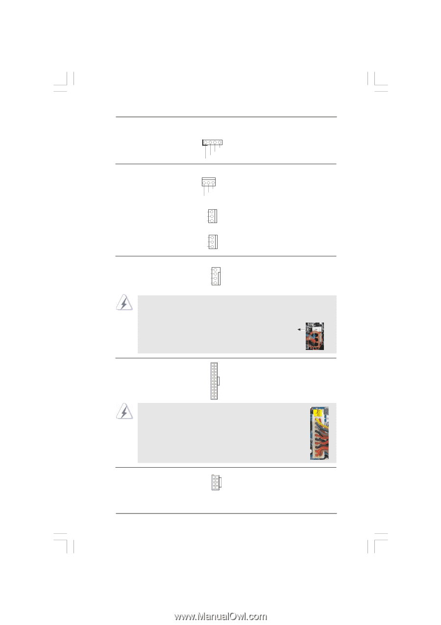
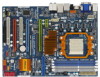
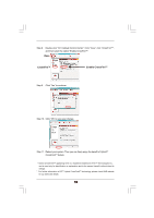
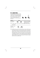
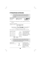
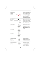
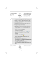
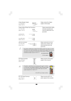
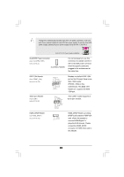
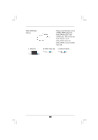
Chassis Speaker Header (4-pin SPEAKER 1) (see p.14 No. 21) 1 SPEAKER DUMMY DUMMY +5V Chassis, NB and Power Fan Connectors (3-pin CHA_FAN1) (see p.14 No. 30) GND +12V CHA_FAN_SPEED (3-pin NB_FAN1) (see p.14 No. 10) NB_FAN_SPEED +12V GND Please connect the chassis speaker to this header. Please connect the fan cables to the fan connectors and match the black wire to the ground pin. (3-pin PWR_FAN1) (see p.14 No. 41) PWR_FAN_SPEED +12V GND CPU Fan Connector (4-pin CPU_FAN1) (see p.14 No. 3) FAN_SPEED_CONTROL 4 CPU_FAN_SPEED 3 +12V 2 GND 1 Please connect the CPU fan cable to this connector and match the black wire to the ground pin. Though this motherboard provides 4-Pin CPU fan (Quiet Fan) support, the 3-Pin CPU fan still can work successfully even without the fan speed control function. If you plan to connect the 3-Pin CPU fan to the CPU fan connector on this motherboard, please connect it to Pin 1-3. Pin 1-3 Connected 3-Pin Fan Installation ATX Power Connector (24-pin ATXPWR1) (see p.14 No. 9) 12 24 Please connect an ATX power supply to this connector. 1 13 Though this motherboard provides 24-pin ATX power connector, 12 24 it can still work if you adopt a traditional 20-pin ATX power supply. To use the 20-pin ATX power supply, please plug your power supply along with Pin 1 and Pin 13. ATX 12V Power Connector (8-pin ATX12V1) (see p.14 No. 1) 20-Pin ATX Power Supply Installation 1 13 4 8 1 5 Please connect an ATX 12V power supply to this connector. 38
-
 1
1 -
2
-
3
-
4
-
5
-
6
-
7
-
8
-
9
-
10
-
11
-
12
-
13
-
14
-
15
-
16
-
17
-
18
-
19
-
20
-
21
-
22
-
23
-
24
-
25
-
26
-
27
-
28
-
29
-
30
-
31
-
32
-
 33
33 -
 34
34 -
 35
35 -
 36
36 -
 37
37 -
 38
38 -
 39
39 -
 40
40 -
 41
41 -
 42
42 -
 43
43 -
44
-
45
-
46
-
47
-
48
-
49
-
50
-
51
-
52
-
53
-
54
-
55
-
56
-
57
-
58
-
59
-
60
-
61
-
62
-
63
-
64
-
65
-
66
-
67
-
68
-
69
-
70
-
71
-
72
-
73
-
74
-
75
-
76
-
77
 |
 |