ASRock NF6-GLAN Quick Installation Guide - Page 15
ASRock, Motherboard
 |
View all ASRock NF6-GLAN manuals
Add to My Manuals
Save this manual to your list of manuals |
Page 15 highlights
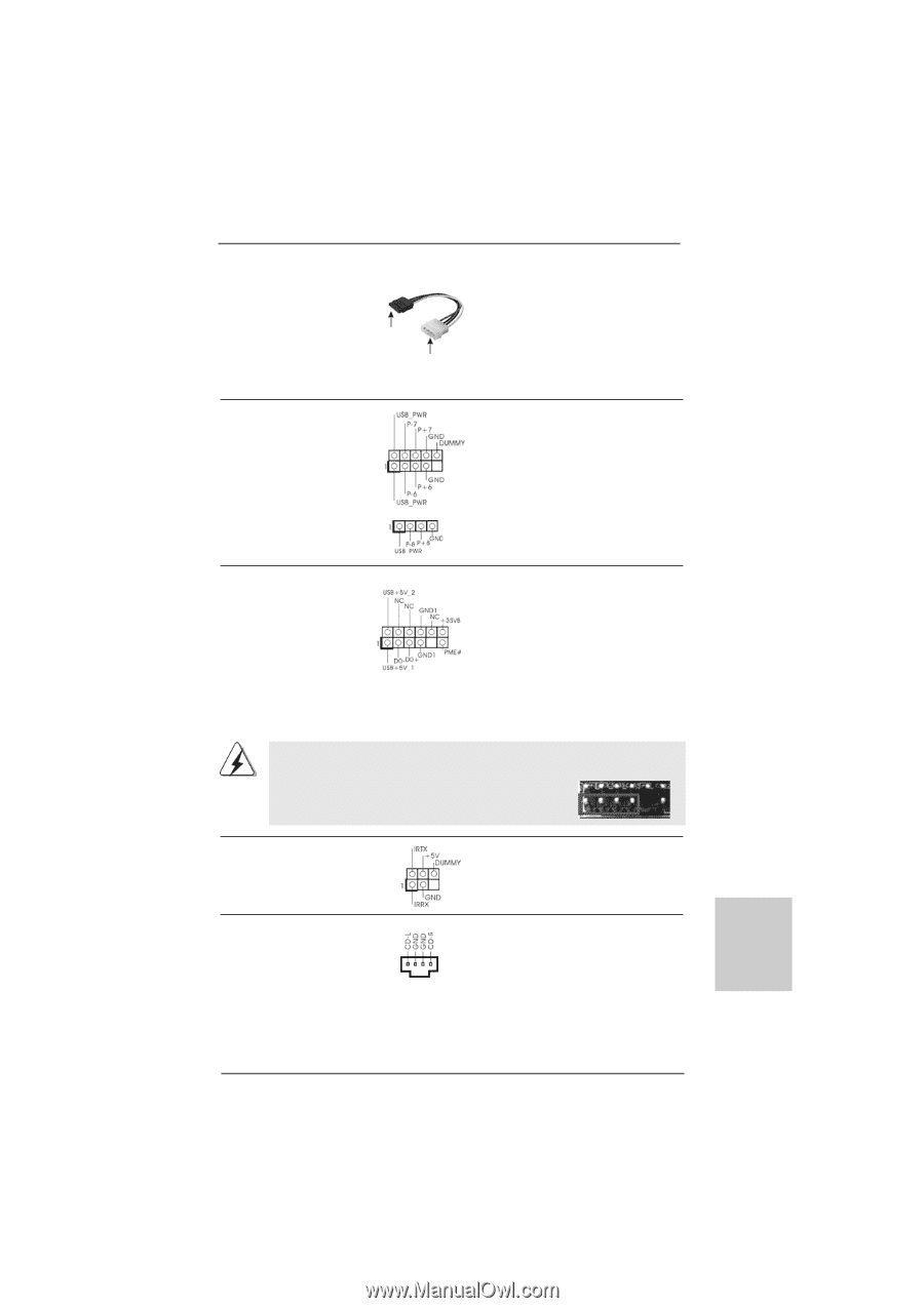
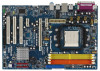
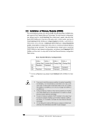
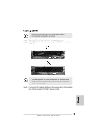
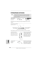
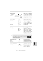
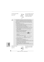
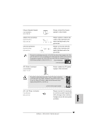
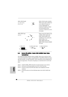
Serial ATA (SATA) Power Cable (Optional) connect to the SATA HDD power connector USB 2.0 Headers (9-pin USB6_7) (see p.2 No. 14) (4-pin USB8) (see p.2 No. 13) connect to the power supply Please connect the black end of SATA power cable to the power connector on each drive. Then connect the white end of SATA power cable to the power connector of the power supply. Besides six default USB 2.0 ports on the I/O panel, there are two USB 2.0 headers on this motherboard. USB6_7 header cansupport two USB 2.0 ports, and USB8 header can support one USB 2.0 port. WiFi Header (11-pin WIFI) (see p.2 No. 25) This header supports WiFi+AP function with ASRock WiFi-802.11g or WiFi-802.11n module, an easy-to-use wireless local area network (WLAN) adapter. It allows you to create a wireless environment and enjoy the convenience of wireless network connectivity. If you don't plan to use WiFi+AP function on this motherboard, this header can be used as a 4-Pin USB 2.0 header to support one USB 2.0 port. To connect the 4-Pin USB device cable to this header, please refer to this picture for proper installation. Infrared Module Header (5-pin IR1) (see p.2 No. 21) Internal Audio Connectors (4-pin CD1) (CD1: see p.2 No. 23) This header supports an optional wireless transmitting and receiving infrared module. This connector allows you to receive stereo audio input CD1 from sound sources such as a CD-ROM, DVD-ROM, TV tuner card, or MPEG card. English 15 ASRock NF6-GLAN Motherboard
-
 1
1 -
2
-
3
-
4
-
5
-
6
-
7
-
8
-
9
-
 10
10 -
 11
11 -
 12
12 -
 13
13 -
 14
14 -
 15
15 -
 16
16 -
 17
17 -
 18
18 -
 19
19 -
 20
20 -
21
-
22
-
23
-
24
-
25
-
26
-
27
-
28
-
29
-
30
-
31
-
32
-
33
-
34
-
35
-
36
-
37
-
38
-
39
-
40
-
41
-
42
-
43
-
44
-
45
-
46
-
47
-
48
-
49
-
50
-
51
-
52
-
53
-
54
-
55
-
56
-
57
-
58
-
59
-
60
-
61
-
62
-
63
-
64
-
65
-
66
-
67
-
68
-
69
-
70
-
71
-
72
-
73
-
74
-
75
-
76
-
77
-
78
-
79
-
80
-
81
-
82
-
83
-
84
-
85
-
86
-
87
-
88
-
89
-
90
-
91
 |
 |