ASRock P45TS Quick Installation Guide - Page 21
This header supports WiFi+AP
 |
View all ASRock P45TS manuals
Add to My Manuals
Save this manual to your list of manuals |
Page 21 highlights
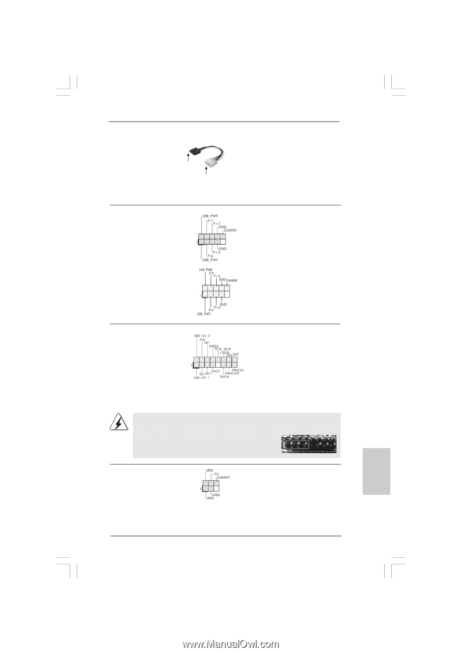
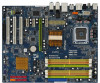
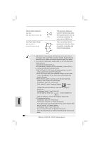
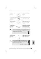
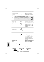
Serial ATA (SATA) Power Cable (Optional) connect to the SATA HDD power connector connect to the power supply USB 2.0 Headers (9-pin USB6_7) (see p.2/3 No. 19) (9-pin USB4_5) (see p.2/3 No. 18) Please connect the black end of SATA power cable to the power connector on each drive. Then connect the white end of SATA power cable to the power connector of the power supply. Besides six default USB 2.0 ports on the I/O panel, there are two USB 2.0 headers on this motherboard. Each USB 2.0 header can support two USB 2.0 ports. WiFi/E Header (15-pin WIFI/E) (see p.2 No. 32 or p.3 No. 31) This header supports WiFi+AP function with ASRock WiFi-802.11g or WiFi-802.11n module, an easy-to-use wireless local area network (WLAN) adapter. It allows you to create a wireless environment and enjoy the convenience of wireless network connectivity. If you don't plan to use WiFi+AP functin on this motherboard, this header can be used as a 4-Pin USB 2.0 header to support one USB 2.0 port. To connect the 4-Pin USB device cable to this header, please refer to this picture for proper installation. Infrared Module Header (5-pin IR1) (see p.2 No. 26 or p.3 No. 25) This header supports an optional wireless transmitting and receiving infrared module. 21 ASRock P45TS-R / P45TS Motherboard English
-
 1
1 -
2
-
3
-
4
-
5
-
6
-
7
-
8
-
9
-
10
-
11
-
12
-
13
-
14
-
15
-
 16
16 -
 17
17 -
 18
18 -
 19
19 -
 20
20 -
 21
21 -
 22
22 -
 23
23 -
 24
24 -
 25
25 -
 26
26 -
27
-
28
-
29
-
30
-
31
-
32
-
33
-
34
-
35
-
36
-
37
-
38
-
39
-
40
-
41
-
42
-
43
-
44
-
45
-
46
-
47
-
48
-
49
-
50
-
51
-
52
-
53
-
54
-
55
-
56
-
57
-
58
-
59
-
60
-
61
-
62
-
63
-
64
-
65
-
66
-
67
-
68
-
69
-
70
-
71
-
72
-
73
-
74
-
75
-
76
-
77
-
78
-
79
-
80
-
81
-
82
-
83
-
84
-
85
-
86
-
87
-
88
-
89
-
90
-
91
-
92
-
93
-
94
-
95
-
96
-
97
-
98
-
99
-
100
-
101
-
102
-
103
-
104
-
105
-
106
-
107
-
108
-
109
-
110
-
111
-
112
-
113
-
114
-
115
-
116
-
117
-
118
-
119
-
120
-
121
-
122
-
123
-
124
-
125
-
126
-
127
-
128
-
129
-
130
-
131
-
132
-
133
-
134
-
135
-
136
 |
 |