ASRock P4i45PE R3.0 User Manual - Page 15
Connectors
 |
View all ASRock P4i45PE R3.0 manuals
Add to My Manuals
Save this manual to your list of manuals |
Page 15 highlights
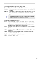
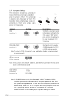
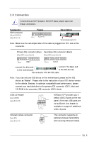
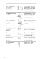
2.8 Connectors Connectors are NOT jumpers. DO NOT place jumper caps over these connectors. Connector FDD connector (33-pin FLOPPY1) (see p.8 item 14) Figure Pin1 FLOPPY1 Description the red-striped side to Pin1 Note: Make sure the red-striped side of the cable is plugged into Pin1 side of the connector. Primary IDE connector (Blue) Secondary IDE connector (Black) (39-pin IDE1, see p.8 item 9) (39-pin IDE2, see p.8 item 8) PIN1 IDE1 PIN1 IDE2 connect the blue end connect the black end to the motherboard to the IDE devices 80-conductor ATA 66/100 cable Note: If you use only one IDE device on this motherboard, please set the IDE device as "Master". Please refer to the instruction of your IDE device vendor for the details. Besides, to optimize compatibility and performance, please connect your hard disk drive to the primary IDE connector (IDE1, blue) and CD-ROM to the secondary IDE connector (IDE2, black). USB 2.0 Header (9-pin USB45) (see p.8 item 18) USB_PWR P-5 P+5 GND DUMMY 1 GND P+4 P-4 USB_PWR ASRock I/OTM provides you 4 default USB 2.0 ports on the rear panel. If the rear USB ports are not sufficient, this header is available to support 2 additional USB 2.0 ports. Infrared module connector (5-pin IR1) (see p.8 item 17) IRTX +5V DUMMY 1 GND IRRX This connector supports an optional wireless transmitting and receiving infrared module. 15
-
 1
1 -
2
-
3
-
4
-
5
-
6
-
7
-
8
-
9
-
 10
10 -
 11
11 -
 12
12 -
 13
13 -
 14
14 -
 15
15 -
 16
16 -
 17
17 -
 18
18 -
 19
19 -
 20
20 -
21
-
22
-
23
-
24
-
25
-
26
-
27
-
28
-
29
-
30
 |
 |
