ASRock P4i65G Quick Installation Guide - Page 14
English - cpu support
 |
View all ASRock P4i65G manuals
Add to My Manuals
Save this manual to your list of manuals |
Page 14 highlights
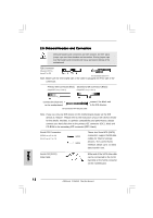
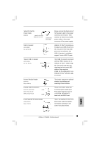
1. +5VA is used for audio power only, please don't connect it to any other power, such as USB. 2. HD (Azalia) audio front panel and AC'97 audio front panel have different pin-definition. Incorrect connection of the audio front panel and the front panel audio header may cause permanent damage to this motherboard. System Panel Header (9-pin PANEL1) (see p.2 No. 17) This header accommodates several system front panel functions. Chassis Speaker Header (4-pin SPEAKER 1) (see p.2 No. 18) Chassis Fan Connector (3-pin CHA_FAN1) (see p.2 No. 16) CPU Fan Connector (3-pin CPU_FAN1) (see p.2 No. 5) ATX Power Connector (20-pin ATXPWR1) (see p.2 No. 7) Please connect the chassis speaker to this header. Please connect the chassis fan cable to this connector and match the black wire to the ground pin. Please connect the CPU fan cable to this connector and match the black wire to the ground pin. Please connect an ATX power supply to this connector. ATX 12V Connector (4-pin ATX12V1) (see p.2 No. 2) Serial port connector (9-pin COM1) (see p.2 item 23) Please note that it is necessary to connect a power supply with ATX 12V plug to this connector so that it can provides sufficient power. Failing to do so will cause the failure to power up. This COM1 connector supports a serial port module. 14 ASRock P4i65G Motherboard English
-
 1
1 -
2
-
3
-
4
-
5
-
6
-
7
-
8
-
 9
9 -
 10
10 -
 11
11 -
 12
12 -
 13
13 -
 14
14 -
 15
15 -
 16
16 -
 17
17 -
 18
18 -
 19
19 -
20
-
21
-
22
-
23
-
24
-
25
-
26
-
27
-
28
-
29
-
30
-
31
-
32
-
33
-
34
-
35
-
36
-
37
-
38
-
39
-
40
-
41
-
42
-
43
-
44
-
45
-
46
-
47
-
48
-
49
-
50
-
51
-
52
-
53
-
54
-
55
-
56
-
57
-
58
-
59
-
60
-
61
-
62
-
63
-
64
-
65
-
66
-
67
-
68
-
69
-
70
-
71
-
72
-
73
-
74
-
75
-
76
-
77
-
78
-
79
-
80
-
81
-
82
-
83
-
84
 |
 |
