ASRock TRX40 Creator User Manual
ASRock TRX40 Creator Manual
 |
View all ASRock TRX40 Creator manuals
Add to My Manuals
Save this manual to your list of manuals |
ASRock TRX40 Creator manual content summary:
- ASRock TRX40 Creator | User Manual - Page 1
- ASRock TRX40 Creator | User Manual - Page 2
change without notice, and should not be constructed as a commitment by ASRock. ASRock assumes no responsibility for any errors or omissions that may appear in CALIFORNIA, USA ONLY The Lithium battery adopted on this motherboard contains Perchlorate, a toxic substance controlled in Perchlorate Best - ASRock TRX40 Creator | User Manual - Page 3
if the goods fail to be of acceptable quality and the failure does not amount to a major failure. If you require assistance please call ASRock Tel : +886-2-28965588 ext.123 (Standard International call charges apply) Manufactured under license under U.S. Patent Nos: 5,956,674; 5,974,380; 6,487,535 - ASRock TRX40 Creator | User Manual - Page 4
CE Warning This device complies with directive 2014/53/EU issued by the Commision of the European Community. This equipment complies with EU radiation exposure limits set forth for an uncontrolled environment. This equipment should be installed and operated with minimum distance 20cm between the - ASRock TRX40 Creator | User Manual - Page 5
Specifications 2 1.3 Motherboard Layout 7 1.4 I/O Panel 9 1.5 WiFi-802.11ax Module and ASRock WiFi 2.4/5 GHz Antenna 11 1.6 USB 3.2 Gen2 x2 Module 12 Chapter 2 Installation 13 2.1 Installing the CPU 14 2.2 Installing the CPU Liquid Cooler 18 2.3 Installation of Memory Modules (DIMM - ASRock TRX40 Creator | User Manual - Page 6
) Module Installation Guide (M2_3) 51 Chapter 3 Software and Utilities Operation 54 3.1 Installing Drivers 54 3.2 ASRock Motherboard Utility (A-Tuning) 55 3.2.1 Installing ASRock Motherboard Utility (A-Tuning) 55 3.2.2 Using ASRock Motherboard Utility (A-Tuning) 55 3.3 ASRock Live Update - ASRock TRX40 Creator | User Manual - Page 7
75 4.4.2 Onboard Devices Configuration 76 4.4.3 Storage Configuration 78 4.4.4 ACPI Configuration 79 4.4.5 Trusted Computing 80 4.4.6 AMD CBS 81 4.4.7 AMD PBS 82 4.4.8 AMD Overclocking 83 4.5 Tools 84 4.6 Hardware Health Event Monitoring Screen 86 4.7 Security Screen 89 4.8 Boot - ASRock TRX40 Creator | User Manual - Page 8
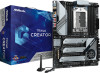
the latest VGA cards and CPU support list on ASRock's website as well. ASRock website http://www.asrock.com. 1.1 Package Contents • ASRock TRX40 Creator Motherboard (ATX Form Factor) • ASRock TRX40 Creator Quick Installation Guide • ASRock TRX40 Creator Support CD • 4 x Serial ATA (SATA) Data Cables - ASRock TRX40 Creator | User Manual - Page 9
Factor • 8 Layer PCB • 2oz Copper PCB CPU • Supports AMD Socket sTRX4 • Intersil Digital PWM • 8 Power Phase design • Supports ASRock Hyper BCLK Engine II Chipset • AMD TRX40 Memory • Quad Channel DDR4 Memory Technology • 8 x DDR4 DIMM Slots • Supports DDR4 4666(OC)+/4600(OC)/4533(OC)/4466 (OC - ASRock TRX40 Creator | User Manual - Page 10
TRX40 Creator Audio LAN • 7.1 CH HD Audio (Realtek ALC4050H+ALC1220) • Premium Blu-ray Audio support • Supports Surge Protection • Supports Purity SoundTM 4 - Nichicon Fine Gold Series Audio Caps - NE5532 Premium Headset Amplifier for Front Panel Audio Connector (Supports up to 600 Ohm headsets) - - ASRock TRX40 Creator | User Manual - Page 11
with LED (ACT/LINK LED and SPEED LED) • 1 x Clear CMOS Button • 1 x BIOS Flashback Button • HD Audio Jacks: Rear Speaker / Central / Line in / Front Speaker / Microphone (Gold Audio Jacks) Storage • 8 x SATA3 6.0 Gb/s Connectors, support RAID (RAID 0, RAID 1 and RAID 10), NCQ, AHCI and Hot Plug - ASRock TRX40 Creator | User Manual - Page 12
TRX40 Creator Connector • 1 x TPM Header • 1 x Power LED and Speaker Header • 2 x RGB LED Headers * Support in total up to 12V/3A, 36W LED Strip • 2 x Addressable LED Headers * Support in total up to 5V/3A, 15W LED Strip • 1 x CPU Fan Connector (4-pin) * The CPU Fan Connector supports the CPU fan - ASRock TRX40 Creator | User Manual - Page 13
UEFI Legal BIOS with GUI support • Supports "Plug and Play" • ACPI 5.1 compliance wake up events • Supports jumperfree • SMBIOS 2.3 support • CPU, detailed product information, please visit our website: http://www.asrock.com Please realize that there is a certain risk involved with overclocking, including adjusting - ASRock TRX40 Creator | User Manual - Page 14
1.3 Motherboard Layout TRX40 Creator M2_1 M2_2 DDR4_D2 (64 bit, 288-pin module) DDR4_D1 (64 bit, 288-pin module) DDR4_C2 (64 bit, 288-pin module) DDR4_C1 (64 bit, 288-pin module) TRX40 CREATOR DDR4_A1 (64 bit, 288-pin module) DDR4_A2 (64 bit, 288-pin module) DDR4_B1 (64 bit, 288-pin module) - ASRock TRX40 Creator | User Manual - Page 15
No. Description 1 CPU Xtreme OC Switch (MOS_PROCHOT1) 2 8 pin 12V Power Connector (ATX12V2) 3 2 x 288-pin DDR4 DIMM Slots (DDR4_D2, DDR4_C2) 4 2 x 288-pin DDR4 DIMM Slots (DDR4_D1, DDR4_C1) 5 2 x 288-pin DDR4 DIMM Slots (DDR4_A1, DDR4_B1) 6 2 x 288-pin DDR4 DIMM Slots (DDR4_A2, DDR4_B2) 7 CPU Fan - ASRock TRX40 Creator | User Manual - Page 16
1.4 I/O Panel 1 TRX40 Creator 24 35 6 7 16 15 14 13 12 11 10 9 8 No. Description No. Ports 7 10G LAN RJ-45 Port 15 USB 3.2 Gen1 Ports (USB32G1_1_2) (AQUANTIA® AQC107)*** 16 BIOS Flashback Button 8 USB 3.2 Gen2x2 Type-C Port * If you use a 2-channel speaker, please connect - ASRock TRX40 Creator | User Manual - Page 17
Blinking Data Activity On Link Speed LED Status Orange Green Description 10Mbps/100Mbps/1Gbps/2.5Gbps /5Gbps connection 10Gbps connection **** ACPI wake-up function is not supported on USB32G2_1_2 ports. English 10 - ASRock TRX40 Creator | User Manual - Page 18
TRX40 Creator 1.5 WiFi-802.11ax Module and ASRock WiFi 2.4/5 GHz Antenna WiFi-802.11ax + BT Module This motherboard comes with an exclusive WiFi 802.11 a/b/g/n/ax + BT v5.0 module (pre-installed on the rear I/O panel) that offers support for WiFi 802.11 a/b/ g/n/ax connectivity standards and - ASRock TRX40 Creator | User Manual - Page 19
and this module Connector • 1 x USB 3.2 Gen2x2 Type-C Port (Supports ESD Protection (ASRock Full Spike Protection)) *For charging Type-A USB devices, we suggest using the Type-A connectors on your motherboard. *This port supports power outputs up to 5V/3A. For charging Type-C USB devices, the - ASRock TRX40 Creator | User Manual - Page 20
TRX40 Creator Chapter 2 Installation This is an ATX form factor motherboard. Before you install the motherboard, study the configuration of your chassis to ensure that the motherboard fits into it. Pre-installation Precautions Take note of the following precautions before you install motherboard - ASRock TRX40 Creator | User Manual - Page 21
2.1 Installing the CPU Tutorial Video Unplug all power cables before installing the CPU. 1 2 14 English - ASRock TRX40 Creator | User Manual - Page 22
TRX40 Creator 3 4 15 English - ASRock TRX40 Creator | User Manual - Page 23
5 Carr ier Frame with CPU Rail Frame Please make sure that the carrier frame with CPU is closely attached to the rail frame while inserting it. Install the orange carrier frame with CPU. Don't separate them. 6 English 16 - ASRock TRX40 Creator | User Manual - Page 24
TRX40 Creator 7 8 17 English - ASRock TRX40 Creator | User Manual - Page 25
2.2 Installing the CPU Liquid Cooler After you install the CPU into this motherboard, it is necessary to install a larger heatsink and cooling fan to dissipate heat. You also need to spray thermal grease between the CPU and the - ASRock TRX40 Creator | User Manual - Page 26
TRX40 Creator 3 4 19 English - ASRock TRX40 Creator | User Manual - Page 27
2.3 Installation of Memory Modules (DIMM) This motherboard provides eight 288-pin DDR4 (Double Data Rate 4) DIMM slots, and supports Quad Channel Memory Technology. 1. For quad channel configuration, you always need to install identical (the same brand, speed, size and chip-type) DDR4 DIMM pairs. 2. - ASRock TRX40 Creator | User Manual - Page 28
TRX40 Creator • If only two memory modules are installed in the DDR4 DIMM slots, then Dual Channel Memory Technology is activated. If three memory modules are installed, then Triple Channel Memory Technology is activated. If more than four memory modules are installed in the DDR4 DIMM slots, then - ASRock TRX40 Creator | User Manual - Page 29
Express Slots) There are 4 PCI Express slots on the motherboard. Before installing an expansion card, please make sure that the Mode For a better thermal environment, please connect a chassis fan to the motherboard's chassis fan connector (CHA_FAN1/WP, CHA_FAN2/WP or CHA_FAN3/WP) when using multiple - ASRock TRX40 Creator | User Manual - Page 30
TRX40 Creator 2.5 Onboard Headers and Connectors Onboard headers and connectors are NOT jumpers. Do NOT place jumper caps over these headers and connectors. Placing jumper caps over the headers and connectors will cause permanent damage to the motherboard. System Panel Header (9-pin PANEL1) (see - ASRock TRX40 Creator | User Manual - Page 31
rate. USB 2.0 Header (9-pin USB_1_2) (see p.7, No. 23) USB_PWR PP+ GND DUMMY 1 GND P+ PUSB_PWR There is one header on this motherboard. This USB 2.0 header can support two ports. USB 3.2 Gen1 Headers (19-pin USB32G1_5_6) (see p.7, No. 22) (19-pin USB32G1_7_8) (see p.7, No. 13) ID IntA_P_D - ASRock TRX40 Creator | User Manual - Page 32
TRX40 Creator Front Panel Type C USB 3.2 Gen2 Header (20-pin F_USB32G2_ TC_1) (see p.7, No. 11) USB Type-C Cable There is one Front Panel Type C USB 3.2 Gen2 Header on this motherboard. This header is used for connecting a USB 3.2 Gen2 module for additional USB 3.2 Gen2 ports. Front Panel Audio - ASRock TRX40 Creator | User Manual - Page 33
fan (Quiet Fan) connector. If you plan to connect a 3-Pin CPU fan, please connect it to Pin 1-3. FAN_SPEED_CONTROL CPU_FAN_SPEED FAN_VOLTAGE GND 1 2 34 This motherboard provides a 4-Pin water cooling CPU fan connector. If you plan to connect a 3-Pin CPU water cooler fan, please connect it to Pin - ASRock TRX40 Creator | User Manual - Page 34
TRX40 Creator Graphics 12V 3V LAD3 PCIRST # FRAM E PCICLK 4 1 6 3 This motherboard provides a 6-pin Graphics 12V power connector. * Install the PSU graphics cards are installed. GN D This connector supports Trusted Platform Module (TPM) system, 1 which instructions on this header. English 27 - ASRock TRX40 Creator | User Manual - Page 35
effects. Caution: Never install the Addressable LED cable in the wrong orientation; otherwise, the cable may be damaged. *Please refer to page 65 for further instructions on this header. English 28 - ASRock TRX40 Creator | User Manual - Page 36
TRX40 Creator 2.6 Smart Switches The motherboard has five smart switches: Power Button, Reset Button, Clear CMOS Button, CPU Xtreme OC Switch and BIOS Flashback Button. Power Button (PWRBTN1) (see p.7, No. 20) Power Button allows users to quickly turn on/off the system. Reset Button (RSTBTN1) ( - ASRock TRX40 Creator | User Manual - Page 37
flash the BIOS. ASRock BIOS Flashback feature allows you to update BIOS without powering on the system, even without CPU. To use the USB BIOS Flashback function, Please follow the steps below. 1. Download the latest BIOS file from ASRock's website : http://www.asrock.com. 2. Copy the BIOS file to - ASRock TRX40 Creator | User Manual - Page 38
TRX40 Creator 2.7 Dr. Debug Dr. Debug is used to provide code information, which makes troubleshooting even easier. Please see the diagrams below for reading the Dr. Debug codes. Code Description 0x10 PEI_CORE_STARTED 0x11 PEI_CAR_CPU_INIT 0x15 PEI_CAR_NB_INIT 0x19 PEI_CAR_SB_INIT 0x31 - ASRock TRX40 Creator | User Manual - Page 39
English 0x63 0x68 0x69 0x6A 0x70 0x71 0x72 0x78 0x79 0x90 0x91 0x92 0x93 0x94 0x95 0x96 0x97 0x98 32 DXE_CPU_INIT DXE_NB_HB_INIT DXE_NB_INIT DXE_NB_SMM_INIT DXE_SB_INIT DXE_SB_SMM_INIT DXE_SB_DEVICES_INIT DXE_ACPI_INIT DXE_CSM_INIT DXE_BDS_STARTED DXE_BDS_CONNECT_DRIVERS DXE_PCI_BUS_BEGIN - ASRock TRX40 Creator | User Manual - Page 40
DXE_USB_RESET DXE_USB_DETECT DXE_USB_ENABLE DXE_IDE_BEGIN DXE_IDE_RESET DXE_IDE_DETECT DXE_IDE_ENABLE DXE_SCSI_BEGIN DXE_SCSI_RESET DXE_SCSI_DETECT DXE_SCSI_ENABLE DXE_SETUP_VERIFYING_PASSWORD DXE_SETUP_START DXE_SETUP_INPUT_WAIT DXE_READY_TO_BOOT DXE_LEGACY_BOOT TRX40 Creator 33 English - ASRock TRX40 Creator | User Manual - Page 41
0xAF 0xB0 0xB1 0xB2 0xB3 0xB4 0xB5 0xB6 0xB7 0xF0 0xF1 0xF2 0xF3 0xF4 0xE0 0xE1 0xE2 DXE_EXIT_BOOT_SERVICES RT_SET_VIRTUAL_ADDRESS_MAP_BEGIN RT_SET_VIRTUAL_ADDRESS_MAP_END DXE_LEGACY_OPROM_INIT DXE_RESET_SYSTEM DXE_USB_HOTPLUG DXE_PCI_BUS_HOTPLUG DXE_NVRAM_CLEANUP DXE_CONFIGURATION_RESET - ASRock TRX40 Creator | User Manual - Page 42
PEI_CPU_MISMATCH PEI_CPU_SELF_TEST_FAILED PEI_CPU_NO_MICROCODE PEI_CPU_ERROR PEI_RESET_NOT_AVAILABLE DXE_CPU_ERROR DXE_NB_ERROR DXE_SB_ERROR DXE_ARCH_PROTOCOL_NOT_AVAILABLE DXE_PCI_BUS_OUT_OF_RESOURCES DXE_LEGACY_OPROM_NO_SPACE DXE_NO_CON_OUT DXE_NO_CON_IN TRX40 Creator 35 English - ASRock TRX40 Creator | User Manual - Page 43
0xD8 0xD9 0xDA 0xDB 0xDC 0xE8 0xE9 0xEA 0xEB DXE_INVALID_PASSWORD DXE_BOOT_OPTION_LOAD_ERROR DXE_BOOT_OPTION_FAILED DXE_FLASH_UPDATE_FAILED DXE_RESET_NOT_AVAILABLE PEI_MEMORY_S3_RESUME_FAILED PEI_S3_RESUME_PPI_NOT_FOUND PEI_S3_BOOT_SCRIPT_ERROR PEI_S3_OS_WAKE_ERROR English 36 - ASRock TRX40 Creator | User Manual - Page 44
TRX40 Creator 2.8 SLITM, 3-Way SLITM and 4-Way SLITM Operation Guide This motherboard supports NVIDIA® SLITM, 3-way SLITM and NVIDIA® certi- fied. 2. Make sure that your graphics card driver supports NVIDIA® SLITM technology. Download the drivers from the NVIDIA® website: www.nvidia.com 3. Make sure - ASRock TRX40 Creator | User Manual - Page 45
if you install NVIDIA® high-bandwidth graphics cards) to the goldfingers on each graphics card. Make sure the ASRock SLI_HB_Bridge_3S Card in place. SLI_HB_Bridge_3S Card ASRock SLI_HB_Bridge_3S Card (For NVIDIA® high-bandwidth graphics cards) Step 4 Connect a VGA cable or a DVI cable to the monitor - ASRock TRX40 Creator | User Manual - Page 46
TRX40 Creator 2.8.2 Installing Three SLITM-Ready Graphics Cards Step 1 Insert one graphics card into PCIE1 slot, another graphics card to PCIE3 slot, and the other graphics card - ASRock TRX40 Creator | User Manual - Page 47
Step 4 Connect a VGA cable or a DVI cable to the monitor connector or the DVI connector of the graphics card that is inserted to PCIE1 slot. 40 English - ASRock TRX40 Creator | User Manual - Page 48
TRX40 Creator 2.8.3 Installing Four SLITM-Ready Graphics Cards Step 1 Insert one graphics card into the PCIE1 slot, another graphics card into the PCIE2 slot, the third graphics - ASRock TRX40 Creator | User Manual - Page 49
Step 4 Connect a VGA cable or a DVI cable to the monitor connector or the DVI connector of the graphics card that is inserted to PCIE1 slot. 42 English - ASRock TRX40 Creator | User Manual - Page 50
TRX40 Creator 2.8.4 Driver Installation and Setup Install the graphics card drivers to your system. After that, you can enable the Multi-Graphics Processing Unit (GPU) in the NVIDIA® nView system tray utility. Please follow the below procedures to enable the multi-GPU. Step 1 Double-click the NVIDIA - ASRock TRX40 Creator | User Manual - Page 51
motherboard supports CrossFireXTM, 3-way CrossFireXTM and 4-way CrossFireXTM that allows you to install up to four identical PCI Express x16 graphics cards. 1. You should only use identical CrossFireXTM-ready graphics cards that are AMD certified. 2. Make sure that your graphics card driver supports - ASRock TRX40 Creator | User Manual - Page 52
TRX40 Creator Step 3 Connect a VGA cable or a DVI cable to the monitor connector or and PCIE4 slots. (The CrossFire Bridge is provided with the graphics card you purchase, not bundled with this motherboard. Please refer to your graphics card vendor for details.) Step 3 Connect a VGA cable or a DVI - ASRock TRX40 Creator | User Manual - Page 53
connect the Radeon graphics cards on PCIE3 and PCIE4 slots. (The CrossFire Bridge is provided with the graphics card you purchase, not bundled with this motherboard. Please refer to your graphics card vendor for details.) Step 3 Connect a VGA cable or a DVI cable to the monitor connector or the DVI - ASRock TRX40 Creator | User Manual - Page 54
TRX40 Creator 2.9.4 Driver Installation and Setup Step 1 Power on your computer and boot into OS. Step 2 Remove the AMD drivers if you have any VGA drivers installed in your system. The Catalyst Uninstaller is an optional download. We recommend using this utility to uninstall any previously - ASRock TRX40 Creator | User Manual - Page 55
Guide (M2_1 and M2_2) The M.2, also known as the Next Generation Form Factor (NGFF), is a small size and versatile card edge connector that aims to replace mPCIe and mSATA. The Hyper M.2 Sockets (M2_1 and M2_2) support (NGFF) Module Step 1 This motherboard supports M.2_SSD (NGFF) module type 2260 - ASRock TRX40 Creator | User Manual - Page 56
TRX40 Creator Step 3 Before installing a M.2 (NGFF) SSD module, please loosen the M.2 standoff that comes with the package. Then hand tighten the standoff into the desired nut location on the motherboard. Align and gently insert the M.2 (NGFF) SSD module into the M.2 slot. Please be aware that the - ASRock TRX40 Creator | User Manual - Page 57
M.2_SSD (NGFF) Module Support List Vendor SanDisk Intel Intel Intel Kingston Samsung Samsung Samsung ADATA PX-512M8PeG/ 512GB WDS512G1X0C-00ENX0 (NVME) / 512GB For the latest updates of M.2_SSD (NFGG) module support list, please visit our website for details: http://www.asrock.com English 50 - ASRock TRX40 Creator | User Manual - Page 58
TRX40 Creator 2.11 M.2_SSD (NGFF) Module Installation Guide (M2_3) The M.2, also known as the Next Generation Form Factor (NGFF), is a small size and versatile card edge connector that aims to replace mPCIe and mSATA. The Hyper M.2 Socket (M2_3) supports M Key type 2230/2242/2260/2280/22110 M.2 - ASRock TRX40 Creator | User Manual - Page 59
A 20o E D NUT2 NUT1 Step 4 Prepare the M.2 standoff that comes with the package. Then hand tighten the standoff into the desired nut location on the motherboard. Align and gently insert the M.2 (NGFF) SSD module into the M.2 slot. Please be aware that the M.2 (NGFF) SSD module only fits in one - ASRock TRX40 Creator | User Manual - Page 60
TRX40 Creator M.2_SSD (NGFF) Module Support List Vendor SanDisk Intel Intel Intel Intel Kingston Samsung Samsung Samsung -00RC30 WDS512G1X0C-00ENX0 (NVME) / 512GB For the latest updates of M.2_SSD (NFGG) module support list, please visit our website for details: http://www.asrock.com English 53 - ASRock TRX40 Creator | User Manual - Page 61
Chapter 3 Software and Utilities Operation 3.1 Installing Drivers The Support CD that comes with the motherboard contains necessary drivers and useful utilities that enhance the motherboard's features. Running The Support CD To begin using the support CD, insert the CD into your CD-ROM drive. The CD - ASRock TRX40 Creator | User Manual - Page 62
TRX40 Creator 3.2 ASRock Motherboard Utility (A-Tuning) ASRock Motherboard Utility (A-Tuning) is ASRock's multi purpose software suite with a new interface, more new features and improved utilities. 3.2.1 Installing ASRock Motherboard Utility (A-Tuning) ASRock Motherboard Utility (A-Tuning) can be - ASRock TRX40 Creator | User Manual - Page 63
OC Tweaker Configurations for overclocking the system. System Info View information about the system. *The System Browser tab may not appear for certain models. 56 English - ASRock TRX40 Creator | User Manual - Page 64
TRX40 Creator FAN-Tastic Tuning Configure up to five different fan speeds using the graph. The fans will automatically shift to the next speed level when the assigned temperature is met. Settings Configure ASRock ASRock Motherboard Utility (A-Tuning). Click to select "Auto run at Windows Startup" if - ASRock TRX40 Creator | User Manual - Page 65
online store for purchasing and downloading software applications for your ASRock computer. You can quickly and easily install various apps and support utilities. With ASRock APP Shop, you can optimize your system and keep your motherboard up to date simply with a few clicks. Double-click utility - ASRock TRX40 Creator | User Manual - Page 66
TRX40 Creator 3.3.2 Apps When the "Apps" tab is selected, you will see all the available apps on up and down to see more apps listed. You can check the price of the app and whether you have already intalled it or not. - The red icon displays the price or "Free" if the app is free of charge. - The - ASRock TRX40 Creator | User Manual - Page 67
Step 3 If you want to install the app, click on the red icon to start downloading. Step 4 When installation completes, you can find the green "Installed" icon appears on the upper right corner. English To uninstall it, simply click on the trash can icon . *The trash icon may not appear for - ASRock TRX40 Creator | User Manual - Page 68
TRX40 Creator Upgrading an App You can only upgrade the apps you have already installed. When there is an available new version for your app, you will - ASRock TRX40 Creator | User Manual - Page 69
" tab is selected, you will see a list of recommended or critical updates for the BIOS or drivers. Please update them all soon. Step 1 Please check the item information before update. Click on Step 2 to see more details. Click to select one or - ASRock TRX40 Creator | User Manual - Page 70
TRX40 Creator 3.3.4 Setting In the "Setting" page, you can change the language, select the server location, and determine if you want to automatically run the ASRock Live Update & APP Shop on Windows startup. 63 English - ASRock TRX40 Creator | User Manual - Page 71
ASRock Polychrome SYNC is a lighting control utility specifically designed for unique individuals with sophisticated tastes to build the motherboard. RGB_LED2 TRX40 CREATOR ON motherboard components. 1. Please note that the RGB LED strips do not come with the package. 2. The RGB LED header supports - ASRock TRX40 Creator | User Manual - Page 72
ON OFF TRX40 CREATOR TRX40 Creator Connecting the Addressable RGB LED Strip Connect your Addressable RGB LED strip to the Addressable LED Headers (ADDR_LED1, ADDR_LED2) on the motherboard. ADDR_LED2 1 GND DO_ADDR VOUT 1 ADDR_LED1 1 GND DO_ADDR VOUT 1. Never install the RGB LED cable in the wrong - ASRock TRX40 Creator | User Manual - Page 73
SYNC utility. Download this utility from the ASRock Live Update & APP Shop and start coloring your PC style your way! Drag the tab to customize your preference. Toggle on/off the RGB LED switch Sync RGB LED effects for all LED regions of the motherboard Select a RGB LED light effect from the - ASRock TRX40 Creator | User Manual - Page 74
TRX40 Creator Chapter 4 UEFI SETUP UTILITY 4.1 Introduction This section explains how to use the UEFI SETUP UTILITY to configure your system. You may run the UEFI SETUP - ASRock TRX40 Creator | User Manual - Page 75
4.1.2 Navigation Keys Use < > key or < > key to choose among the selections on the menu bar, and use < > key or < > key to move the cursor up or down to select items, then press to get into the sub screen. You can also use the mouse to click your required item. Please check the following - ASRock TRX40 Creator | User Manual - Page 76
TRX40 Creator 4.2 Main Screen When you enter the UEFI SETUP UTILITY, the Main screen will appear and display the system overview. 69 English - ASRock TRX40 Creator | User Manual - Page 77
Mode This item can be used to disable symmetric multithreading. To re-enable SMT, a power cycle is needed after selecting [Auto]. Warning: S3 is not supported on systems where SMT is disabled. 70 English - ASRock TRX40 Creator | User Manual - Page 78
TRX40 Creator CPU Frequency and Voltage (VID) Change If this item is set to [Manual], the multiplier and voltage will be set based on user selection. Final result is depending on the CPU's capability. SoC/Uncore OC Voltage Specify the SoC/Uncore voltage (VDD_SOC) in mV to support memory and Infinity - ASRock TRX40 Creator | User Manual - Page 79
CPU Vcore Load-Line Calibration CPU Load-Line Calibration helps prevent CPU voltage droop when the system is under heavy loading. CPU VDDCR_SOC Voltage Configure the voltage for the VID-requested VDDCR_SOC supply level. CPU VDDCR_SOC Load-Line Calibration VDDCR_SOC Load-Line Calibration helps - ASRock TRX40 Creator | User Manual - Page 80
TRX40 Creator PREM VDD_CLDO Voltage Use this to select PREM VDD_CLDO Voltage. The default value is [Auto]. PREM VDDCR_SOC Voltage Use this to select PREM VDDCR_SOC Voltage. - ASRock TRX40 Creator | User Manual - Page 81
AMD Overclocking. Setting wrong values in this section may cause the system to malfunction. UEFI Configuration Active Page on Entry Select the default page when entering the UEFI setup utility. Full HD UEFI When [Auto] is selected, the resolution will be set to 1920 x 1080 if the monitor supports - ASRock TRX40 Creator | User Manual - Page 82
CPU Configuration TRX40 Creator SVM Mode When this is set to [Enabled], a VMM (Virtual Machine Architecture)can utilize the additional hardware capabilities provided by AMD-V. The [Auto]. Warning: S3 is not supported on systems where SMT is disabled. AMD fTPM Switch Use this to enable or disable - ASRock TRX40 Creator | User Manual - Page 83
4.4.2 Onboard Devices Configuration Turn On LED in S5 Turn on/off the LED in the ACPI S5 state. SR-IOV Support Enable/disable the SR-IOV (Single Root IO Virtualization Support) if the system has SR-IOV capable PCIe devices. Restore on AC/Power Loss Select the power state after a power failure. If - ASRock TRX40 Creator | User Manual - Page 84
Swing setting. Equalization Setting (RX) Configure the equalization setting. Flat Gain Setting (RX) Configure the Flat Gain setting. Swing Setting (RX) Configure the Swing setting. TRX40 Creator English 77 - ASRock TRX40 Creator | User Manual - Page 85
4.4.3 Storage Configuration SATA Controller(s) AHCI: Supports new features that improve performance. RAID: Combine multiple disk drives into a logical unit. 78 English - ASRock TRX40 Creator | User Manual - Page 86
4.4.4 ACPI Configuration TRX40 Creator Suspend to RAM It is recommended to select auto for ACPI S3 power saving. Deep Sleep Configure deep sleep mode for power saving when the computer is shut down. PS/2 Keyboard S4/S5 Wakeup Support Allow the system to be waked up by a PS/2 Keyboard in S4/S5. - ASRock TRX40 Creator | User Manual - Page 87
4.4.5 Trusted Computing Security Device Support Enable or disable BIOS support for security device. 80 English - ASRock TRX40 Creator | User Manual - Page 88
4.4.6 AMD CBS TRX40 Creator The AMD CBS menu accesses AMD specific features. English 81 - ASRock TRX40 Creator | User Manual - Page 89
4.4.7 AMD PBS The AMD PBS menu accesses AMD specific features. 82 English - ASRock TRX40 Creator | User Manual - Page 90
4.4.8 AMD Overclocking TRX40 Creator The AMD Overclocking menu accesses options for configuring CPU frequency and voltage. English 83 - ASRock TRX40 Creator | User Manual - Page 91
Flash Save UEFI files in your USB storage device and run Instant Flash to update your UEFI. Internet Flash - DHCP (Auto IP), Auto ASRock Internet Flash downloads and updates the latest UEFI firmware version from our servers for you. Please setup network configuration before using Internet Flash - ASRock TRX40 Creator | User Manual - Page 92
Network Configuration Use this to configure internet connection settings for Internet Flash. TRX40 Creator Internet Setting Enable or disable sound effects in the setup utility. UEFI Download Server Select a server to download the UEFI firmware. English 85 - ASRock TRX40 Creator | User Manual - Page 93
Monitoring Screen This section allows you to monitor the status of the hardware on your system, including the parameters of the CPU temperature, motherboard temperature, fan speed and voltage. Fan Tuning Measure Fan Min Duty Cycle. Fan-Tastic Tuning Select a fan mode for CPU Fans 1&2, or choose - ASRock TRX40 Creator | User Manual - Page 94
TRX40 Creator CPU Fan 2 Setting Select a fan mode for CPU Fan 2, or choose Customize to set 5 CPU temperatures and assign a respective fan speed for each temperature. CPU - ASRock TRX40 Creator | User Manual - Page 95
temperatures and assign a respective fan speed for each temperature. Over Temperature Protection When Over Temperature Protection is enabled, the system automatically shuts down when the motherboard is overheated. 88 English - ASRock TRX40 Creator | User Manual - Page 96
TRX40 Creator 4.7 Security Screen In this section you may set or change the supervisor/user password for the system. You may also clear the user change the settings in the UEFI Setup Utility. Leave it blank and press enter to remove the password. Secure Boot Enable to support Secure Boot. 89 English - ASRock TRX40 Creator | User Manual - Page 97
4.8 Boot Screen This section displays the available devices on your system for you to configure the boot settings and the boot priority. Boot From Onboard LAN Allow the system to be waked up by the onboard LAN. Boot Beep Select whether the Boot Beep should be turned on or off when the system boots - ASRock TRX40 Creator | User Manual - Page 98
TRX40 Creator Fast Boot Fast Boot minimizes your computer's boot time. In fast mode you may not boot from an USB storage device. CSM (Compatibility Support Module) CSM Enable to launch the Compatibility Support Module. Please do not disable unless you're running a WHCK test. Above 4G Decoding Enable - ASRock TRX40 Creator | User Manual - Page 99
4.9 Exit Screen Save Changes and Exit When you select this option the following message, "Save configuration changes and exit setup?" will pop out. Select [OK] to save changes and exit the UEFI SETUP UTILITY. Discard Changes and Exit When you select this option the following message, "Discard - ASRock TRX40 Creator | User Manual - Page 100
dealer for further information. For technical questions, please submit a support request form at https://event.asrock.com/tsd.asp ASRock Incorporation 2F., No.37, Sec. 2, Jhongyang S. Rd., Beitou District, Taipei City 112, Taiwan (R.O.C.) ASRock EUROPE B.V. Bijsterhuizen 11-11 6546 AR Nijmegen The - ASRock TRX40 Creator | User Manual - Page 101
FCC Part 2 Section 2.1077(a) Responsible Party Name: ASRock Incorporation Address: 13848 Magnolia Ave, Chino, CA91710 Phone/Fax No: +1-909-590-8308/+1-909-590-1026 hereby declares that the product Product Name : Motherboard Model Number : TRX40 Creator Conforms to the following speci cations: FCC - ASRock TRX40 Creator | User Manual - Page 102
EU Declaration of Conformity For the following equipment: Motherboard (Product Name) TRX40 Creator / ASRock (Model Designation / Trade Name) ASRock Incorporation (Manufacturer Name) 2F., No.37, Sec. 2, Jhongyang S. Rd., Beitou District, Taipei City 112, Taiwan (R.O.C.) (Manufacturer Address)
-
 1
1 -
 2
2 -
 3
3 -
 4
4 -
 5
5 -
 6
6 -
 7
7 -
8
-
9
-
10
-
11
-
12
-
13
-
14
-
15
-
16
-
17
-
18
-
19
-
20
-
21
-
22
-
23
-
24
-
25
-
26
-
27
-
28
-
29
-
30
-
31
-
32
-
33
-
34
-
35
-
36
-
37
-
38
-
39
-
40
-
41
-
42
-
43
-
44
-
45
-
46
-
47
-
48
-
49
-
50
-
51
-
52
-
53
-
54
-
55
-
56
-
57
-
58
-
59
-
60
-
61
-
62
-
63
-
64
-
65
-
66
-
67
-
68
-
69
-
70
-
71
-
72
-
73
-
74
-
75
-
76
-
77
-
78
-
79
-
80
-
81
-
82
-
83
-
84
-
85
-
86
-
87
-
88
-
89
-
90
-
91
-
92
-
93
-
94
-
95
-
96
-
97
-
98
-
99
-
100
-
101
-
102
 |
 |