ASRock X58 Deluxe3 User Manual - Page 34
Step 3. Connect the chassis HDD LED lead to ASRock SATA3 Card LED header
 |
View all ASRock X58 Deluxe3 manuals
Add to My Manuals
Save this manual to your list of manuals |
Page 34 highlights
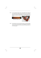
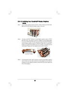
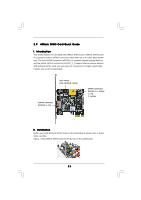
Step 2. If you want to use external storage function, please connect the eSATA cable to the red eSATAIII connector (eSATAIII_1) and the external storage device. If you want to use internal storage function, please connect the SATA data cables to the yellow SATAIII connectors (SATAIII_1_2) and the HDDs. 1. If you use single SATAIII HDD, it is recommended to connect it to SATAIII_1 (top) connector. 2. The red eSATAIII connector (eSATAIII_1) and SATAIII_2 (bottom) connector cannot work simultaneously. You can only use either one of them. or Step 3. Connect the chassis HDD LED lead to ASRock SATA3 Card LED header (HDLED-_CHA and HDLED+_CHA). Before connecting, please consult the chassis manual for the electrode of the HDD LED lead. Make sure you connect the HDD LED lead to the corresponding electrode pin of LED header. Step 4. Connect the bundled motherboard LED lead to ASRock SATA3 Card LED header (LED-_MB and LED+_MB) and the system panel header (HDLEDand HDLED+) on this motherboard. For the bundled motherboard LED lead, the blue lead is "+" electrode, and the black lead is "-" electrode. Make sure you connect the correct lead to ASRock SATA3 Card and system panel header. 34
-
 1
1 -
2
-
3
-
4
-
5
-
6
-
7
-
8
-
9
-
10
-
11
-
12
-
13
-
14
-
15
-
16
-
17
-
18
-
19
-
20
-
21
-
22
-
23
-
24
-
25
-
26
-
27
-
28
-
 29
29 -
 30
30 -
 31
31 -
 32
32 -
 33
33 -
 34
34 -
 35
35 -
 36
36 -
 37
37 -
 38
38 -
 39
39 -
40
-
41
-
42
-
43
-
44
-
45
-
46
-
47
-
48
-
49
-
50
-
51
-
52
-
53
-
54
-
55
-
56
-
57
-
58
-
59
-
60
-
61
-
62
-
63
-
64
-
65
-
66
-
67
-
68
-
69
-
70
-
71
-
72
-
73
-
74
-
75
 |
 |
