ASRock X99 Extreme11 User Manual - Page 30
Please connect the ´DD Saver
 |
View all ASRock X99 Extreme11 manuals
Add to My Manuals
Save this manual to your list of manuals |
Page 30 highlights
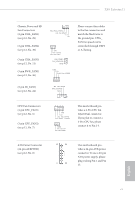
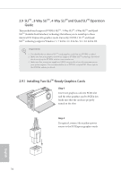
ATX 12V Power Connector (8-pin ATX12V1) (see p.12, No. 3) 8 5 4 1 PCIe Power Connectors (4-pin PCIE_PWR1) (see p.12, No. 37) (4-pin PCIE_PWR2) (see p.12, No. 34) GND +12V DETECT his motherboard provides an 8-pin ATX 12V power connector. To use a 4-pin ATX power supply, please plug it along Pin 1 and Pin 5. Please connect a 4 pin molex power cable to this connector when more than three graphics cards are installed. HDD Saver Connector (4-pin SATA_PWR_1) (see p.12, No. 23) Serial Port Header (9-pin COM1) (see p.12, No. 33) 1 RRXD1 DDTR#1 DDSR#1 CCTS#1 1 RRI#1 RRTS#1 GND TTXD1 DDCD#1 Please connect the HDD Saver Cable to this connector to manage the power state of HDD. his COM1 header supports a serial port module. English 30
-
 1
1 -
2
-
3
-
4
-
5
-
6
-
7
-
8
-
9
-
10
-
11
-
12
-
13
-
14
-
15
-
16
-
17
-
18
-
19
-
20
-
21
-
22
-
23
-
24
-
 25
25 -
 26
26 -
 27
27 -
 28
28 -
 29
29 -
 30
30 -
 31
31 -
 32
32 -
 33
33 -
 34
34 -
 35
35 -
36
-
37
-
38
-
39
-
40
-
41
-
42
-
43
-
44
-
45
-
46
-
47
-
48
-
49
-
50
-
51
-
52
-
53
-
54
-
55
-
56
-
57
-
58
-
59
-
60
-
61
-
62
-
63
-
64
-
65
-
66
-
67
-
68
-
69
-
70
-
71
-
72
-
73
-
74
-
75
-
76
-
77
-
78
-
79
-
80
-
81
-
82
-
83
-
84
-
85
-
86
-
87
-
88
-
89
-
90
-
91
-
92
-
93
-
94
-
95
-
96
-
97
-
98
-
99
-
100
 |
 |

30
English
ATX 12V Power
Connector
(8-pin ATX12V1)
(see p.12, No. 3)
His motherboard pro-
vides an 8-pin ATX 12V
power connector. To use a
4-pin ATX power supply,
please plug it along Pin 1
and Pin 5.
PCIe Power Connectors
(4-pin PCIE_PWR1)
(see p.12, No. 37)
(4-pin PCIE_PWR2)
(see p.12, No. 34)
Please connect a 4 pin molex
power cable to this connector
when more than three graphics
cards are installed.
´DD Saver Connector
(4-pin SATA_PWR_1)
(see p.12, No. 23)
Please connect the ´DD Saver
Cable to this connector to
manage the power state of ´DD.
Serial Port ´eader
(9-pin COM1)
(see p.12, No. 33)
His COM1 header
supports a serial port
module.
CCTS#1
RRTS#1
DDSR#1
DDTR#1
RRXD1
GND
TTXD1
DDCD#1
1
RRI#1
4
1
8
5
1
+12V DETECT
GND