ASRock Z270 Pro4 User Manual - Page 60
CPU Internal PLL Voltage, DRAM Activating Power Supply
 |
View all ASRock Z270 Pro4 manuals
Add to My Manuals
Save this manual to your list of manuals |
Page 60 highlights
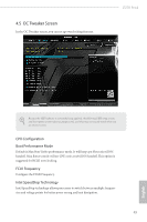
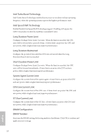
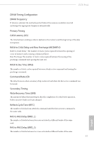
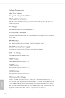
Voltage Configuration CPU Vcore Voltage Configure the voltage for the CPU Vcore. CPU Load-Line Calibration CPU Load-Line Calibration helps prevent CPU voltage droop when the system is under heavy load. GT Voltage Configure the voltage for the integrated GPU. GT Load-Line Calibration GT Load-Line Calibration helps prevent GT voltage droop when the system is under heavy load. DRAM Voltage Use this to configure DRAM Voltage. The default value is [Auto]. DRAM Activating Power Supply Configure the voltage for the DRAM Activating Power Supply. PCH +1.0 Voltage Configure the chipset voltage (1.0V). VCCIO Voltage Configure the voltage for the VCCIO. VCCST Voltage Configure the voltage for the VCCST. VCCSA Voltage Configure the voltage for the VCCSA. CPU Internal PLL Voltage Default is 0.900V. Each step is 0.015V. Adding 9- 15 steps will helps CPU PLL to lock internal clock during High frequency under Ln2 cooling. For example: 1.020V - 1.125V will be proper value. But the voltage level will be different on each processor. User has to find the best value for your own processor. CPU Vcore Voltage must higher than CPU Internal PLL Voltage, or your processor will hang. 54 English
-
 1
1 -
2
-
3
-
4
-
5
-
6
-
7
-
8
-
9
-
10
-
11
-
12
-
13
-
14
-
15
-
16
-
17
-
18
-
19
-
20
-
21
-
22
-
23
-
24
-
25
-
26
-
27
-
28
-
29
-
30
-
31
-
32
-
33
-
34
-
35
-
36
-
37
-
38
-
39
-
40
-
41
-
42
-
43
-
44
-
45
-
46
-
47
-
48
-
49
-
50
-
51
-
52
-
53
-
54
-
 55
55 -
 56
56 -
 57
57 -
 58
58 -
 59
59 -
 60
60 -
 61
61 -
 62
62 -
 63
63 -
 64
64 -
 65
65 -
66
-
67
-
68
-
69
-
70
-
71
-
72
-
73
-
74
-
75
-
76
-
77
-
78
-
79
-
80
-
81
-
82
-
83
-
84
-
85
-
86
 |
 |
