ASRock Z370M Pro4 User Manual - Page 28
Platform Module TPM system, Print Port Header
 |
View all ASRock Z370M Pro4 manuals
Add to My Manuals
Save this manual to your list of manuals |
Page 28 highlights
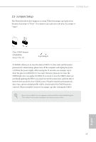
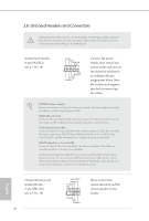
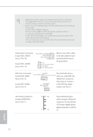
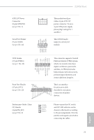
ATX 12V Power Connector (8-pin ATX12V1) (see p.7, No. 1) Serial Port Header (9-pin COM1) (see p.7, No. 24) Z370M Pro4 8 5 This motherboard pro- vides a 8-pin ATX 12V power connector. To use a 4 1 4-pin ATX power supply, please plug it along Pin 1 and Pin 5. This COM1 header supports a serial port module. GN D +3VS B LAD0 +3V LAD3 PCIRST # FRAM E PCICLK TPM Header (17-pin TPMS1) (see p.7, No. 22) GND SERIRQ # S_PWRDWN # GN D LAD1 LAD2 SMB_DATA_MAIN SMB_CLK_MAIN GN D This connector supports Trusted Platform Module (TPM) system, 1 which can securely store keys, digital certificates, passwords, and data. A TPM system also helps enhance network security, protects digital identities, and ensures platform integrity. Print Port Header (25-pin LPT1) (see p.7, No. 23) AFD# ERROR# PINIT# SLIN# GND 1 SPD7 SPD6 ACK# SPD5 BUSY SPD4 PE SPD3 SLCT SPD2 SPD1 SPD0 STB# This is an interface for print port cable that allows convenient connection of printer devices. Performance Mode / Easy OC Header (4-pin PM_EO) (see p.7, No. 6) Please connect the OC switch and OC LED indicator on the chassis to this header according to the pin assignments. Note the positive and negative pins before connecting the cables. English 23
-
 1
1 -
2
-
3
-
4
-
5
-
6
-
7
-
8
-
9
-
10
-
11
-
12
-
13
-
14
-
15
-
16
-
17
-
18
-
19
-
20
-
21
-
22
-
 23
23 -
 24
24 -
 25
25 -
 26
26 -
 27
27 -
 28
28 -
 29
29 -
 30
30 -
 31
31 -
 32
32 -
 33
33 -
34
-
35
-
36
-
37
-
38
-
39
-
40
-
41
-
42
-
43
-
44
-
45
-
46
-
47
-
48
-
49
-
50
-
51
-
52
-
53
-
54
-
55
-
56
-
57
-
58
-
59
-
60
-
61
-
62
-
63
-
64
-
65
-
66
-
67
-
68
-
69
-
70
-
71
-
72
-
73
-
74
-
75
-
76
-
77
-
78
-
79
-
80
-
81
-
82
-
83
-
84
-
85
-
86
 |
 |
