ASRock Z690M-ITX/ax User Manual - Page 33
Caution: Never install the RGB, Warning: Please make
 |
View all ASRock Z690M-ITX/ax manuals
Add to My Manuals
Save this manual to your list of manuals |
Page 33 highlights
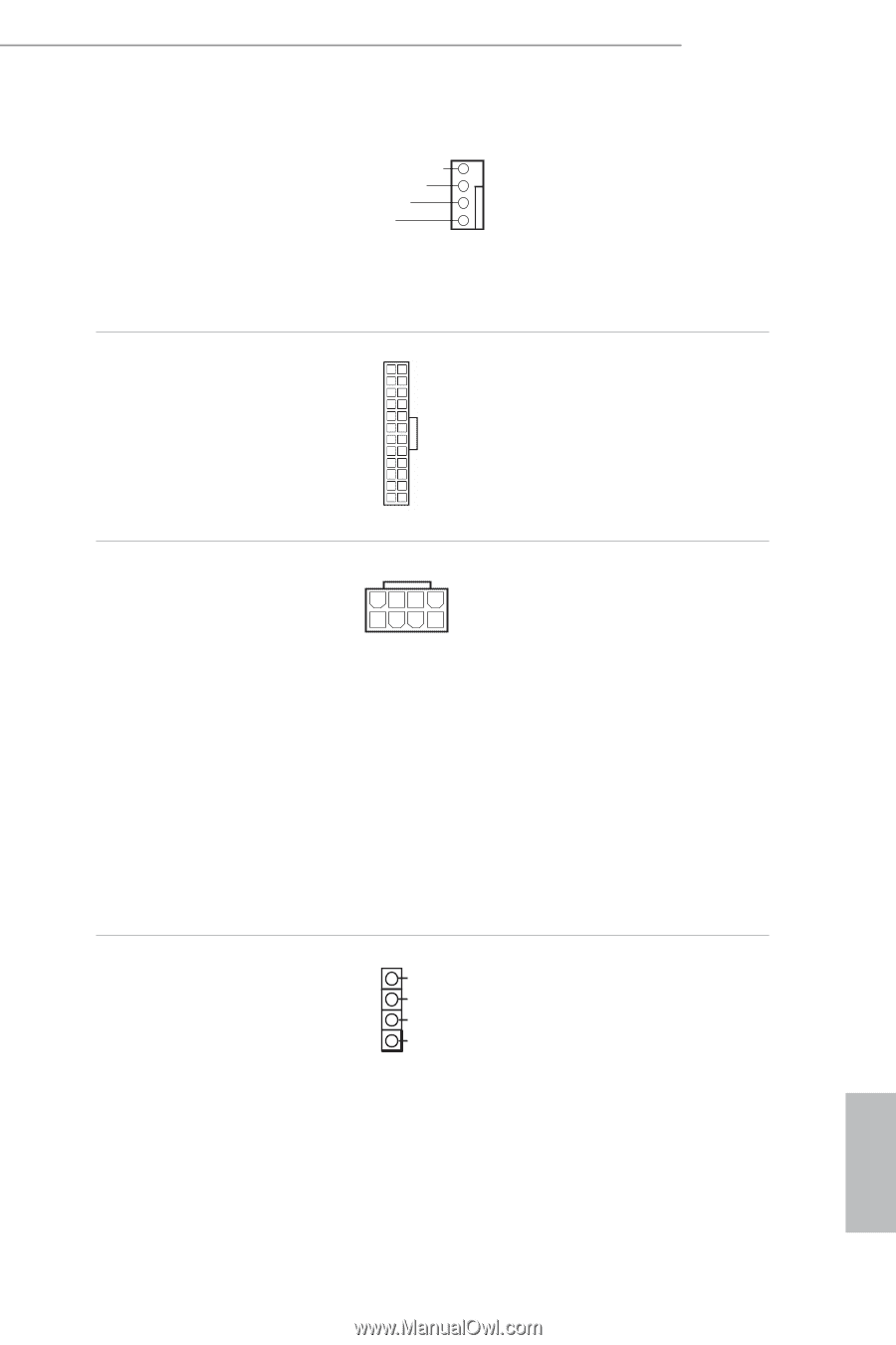
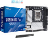
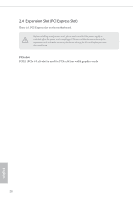
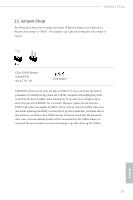
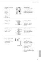
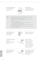
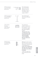
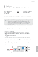
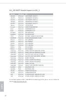
Z690M-ITX/ax CPU Fan Connector (4-pin CPU_FAN1) (see p.7, No. 3) FAN_SPEED_CONTROL FAN_SPEED +12V GND 4 This motherboard pro3 vides a 4-Pin CPU fan 2 1 (Quiet Fan) connector. If you plan to connect a 3-Pin CPU fan, please connect it to Pin 1-3. ATX Power Connector (24-pin ATXPWR1) (see p.7, No. 6) 12 24 This motherboard provides a 24-pin ATX power connector. 1 13 ATX 12V Power Connector (8-pin ATX12V1) (see p.7, No. 2) RGB LED Header (4-pin RGB_LED1) (see p.7, No. 5) 8 5 4 1 B R G 12V 1 This motherboard provides a 8-pin ATX 12V power connector. To use a 4-pin ATX power supply, please plug it along Pin 1 and Pin 5. *Warning: Please make sure that the power cable connected is for the CPU and not the graphics card. Do not plug the PCIe power cable to this connector. RGB header is used to connect RGB LED extension cable which allows users to choose from various LED lighting effects. Caution: Never install the RGB LED cable in the wrong orientation; otherwise, the cable may be damaged. * Please refer to page 44 for further instructions on this header. 25 English
-
 1
1 -
2
-
3
-
4
-
5
-
6
-
7
-
8
-
9
-
10
-
11
-
12
-
13
-
14
-
15
-
16
-
17
-
18
-
19
-
20
-
21
-
22
-
23
-
24
-
25
-
26
-
27
-
 28
28 -
 29
29 -
 30
30 -
 31
31 -
 32
32 -
 33
33 -
 34
34 -
 35
35 -
 36
36 -
 37
37 -
 38
38 -
39
-
40
-
41
-
42
-
43
-
44
-
45
-
46
-
47
-
48
-
49
-
50
-
51
-
52
-
53
-
54
-
55
-
56
-
57
-
58
-
59
-
60
-
61
-
62
-
63
-
64
-
65
-
66
-
67
-
68
-
69
-
70
-
71
-
72
-
73
-
74
-
75
-
76
-
77
-
78
-
79
-
80
-
81
-
82
-
83
-
84
-
85
-
86
-
87
-
88
-
89
-
90
-
91
-
92
-
93
-
94
-
95
-
96
-
97
-
98
 |
 |