ASRock Z790 PG-ITX/TB4 User Manual - Page 48
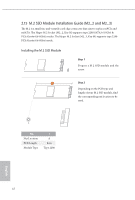
Step 6, Step 7, Step 8
 |
View all ASRock Z790 PG-ITX/TB4 manuals
Add to My Manuals
Save this manual to your list of manuals |
Page 48 highlights
Step 6 Carefully paste the thermal pad on the M.2 module. NUT2 NUT1 NUT2 NUT1 Step 7 Remove the plastic liner from the thermal pad. Step 8 Install the motherboard into the computer case, with the thermal pad on the back side of the motherboard adhered to the chassis. Note: The pad making full contact with the metal plate achieves a better cooling effect. Do not use a hollow-out chassis since it cannot dissipate heat effectively. For the latest updates of M.2 SSD module support list, please visit our website for details: http://www.asrock.com English 44
-
 1
1 -
2
-
3
-
4
-
5
-
6
-
7
-
8
-
9
-
10
-
11
-
12
-
13
-
14
-
15
-
16
-
17
-
18
-
19
-
20
-
21
-
22
-
23
-
24
-
25
-
26
-
27
-
28
-
29
-
30
-
31
-
32
-
33
-
34
-
35
-
36
-
37
-
38
-
39
-
40
-
41
-
42
-
 43
43 -
 44
44 -
 45
45 -
 46
46 -
 47
47 -
 48
48 -
 49
49 -
 50
50 -
 51
51 -
 52
52 -
 53
53 -
54
 |
 |

English
44
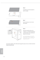
For the latest updates of M.2 SSD module support list, please visit our website for details:
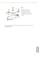
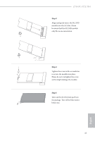
Step 6
Carefully paste the thermal pad on
the M.2 module.
Step 7
Remove the plastic liner from the
thermal pad.
Step 8
Install the motherboard into the
computer case, with the thermal pad
on the back side of the motherboard
adhered to the chassis.
Note: °e pad making full contact with the
metal plate achieves a better cooling effect. Do
not use a hollow-out chassis since it cannot
dissipate heat effectively.
NUT1
NUT2
NUT1
NUT2