ASRock Z790 PG-ITX/TB4 User Manual - Page 9
Z790 PG-ITX/TB4
 |
View all ASRock Z790 PG-ITX/TB4 manuals
Add to My Manuals
Save this manual to your list of manuals |
Page 9 highlights
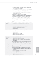
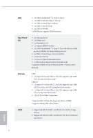
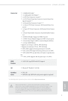
Z790 PG-ITX/TB4 Connector • 1 x RGB LED Header* • 1 x Addressable LED Header** • 1 x CPU Fan Connector (4-pin)*** • 1 x CPU/Water Pump Fan Connector (4-pin) (Smart Fan Speed Control)**** • 1 x Chassis Fan Connector (4-pin)***** • 1 x 24 pin ATX Power Connector (Hi-Density Power Con- nector) • 1 x 8 pin 12V Power Connector (Hi-Density Power Connec- tor) • 1 x Front Panel Audio Connector (15μ Gold Audio Connec- tor) • 1 x USB 2.0 Header (Supports 2 USB 2.0 ports) • 1 x USB 3.2 Gen1 Header (Supports 2 USB 3.2 Gen1 ports) • 1 x Front Panel Type C USB 3.2 Gen2x2 Header (20 Gb/s) • 1 x Clear CMOS Button * Supports in total up to 12V/3A, 36W LED Strip ** Supports in total up to 5V/3A, 15W LED Strip *** CPU_FAN1 supports the fan power up to 1A (12W). **** CPU_FAN2/WP supports the fan power up to 2A (24W). **** CPU_FAN2/WP can auto detect if 3-pin or 4-pin fan is in use. ***** CHA_FAN1 supports the fan power up to 1A (12W). BIOS Feature • AMI UEFI Legal BIOS with GUI support OS • Microsoft® Windows® 11 64-bit Certifications • FCC, CE • ErP/EuP ready (ErP/EuP ready power supply is required) * For detailed product information, please visit our website: http://www.asrock.com Please realize that there is a certain risk involved with overclocking, including adjusting the setting in the BIOS, applying Untied Overclocking Technology, or using third-party overclocking tools. Overclocking may affect your system's stability, or even cause damage to the components and devices of your system. It should be done at your own risk and expense. We are not responsible for possible damage caused by overclocking. 5 English
-
 1
1 -
2
-
3
-
 4
4 -
 5
5 -
 6
6 -
 7
7 -
 8
8 -
 9
9 -
 10
10 -
 11
11 -
 12
12 -
 13
13 -
 14
14 -
15
-
16
-
17
-
18
-
19
-
20
-
21
-
22
-
23
-
24
-
25
-
26
-
27
-
28
-
29
-
30
-
31
-
32
-
33
-
34
-
35
-
36
-
37
-
38
-
39
-
40
-
41
-
42
-
43
-
44
-
45
-
46
-
47
-
48
-
49
-
50
-
51
-
52
-
53
-
54
 |
 |
