Acer AL1911 AL1911 User Guide - Page 3
Interface for Arm Applications, Cable Installation, Connecting the Display to your Computer, - instructions
 |
View all Acer AL1911 manuals
Add to My Manuals
Save this manual to your list of manuals |
Page 3 highlights
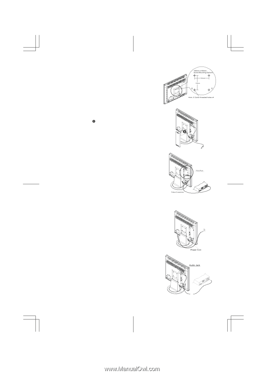
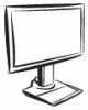
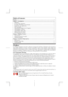
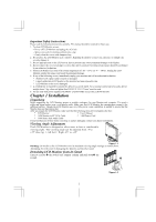
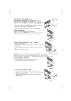
Interface for Arm Applications Before installing to mounting device, please refer to Fig.1-2. The rear of this LCD display has four integrated 4 mm, 0.7 pitches threaded nuts, as well as four 5 mm access holes in the plastic covering as illustrated in Figure 1-3. These specifications meet the VESA Flat Panel Monitor Physical Mounting Interface Standard (paragraphs 2.1 and 2.1.3, version 1, dated 13 November 1997). Note :Please using Ø 4mm x 8mm (L) screw for this application. Cable Installation Please follow these instructions to install the cables. 1. Remove the back panel n from the rear of the monitor.(See Fig. 1-4) 2. Place the signal cable, the audio cable into their correct socket. Figure 1-3 Connecting the Display to your Computer 1. Power off your computer. 2. Connect one end of the signal cable to the LCD Monitor's VGA port. (See Fig 1-5) 3. Connect the other end of the signal cable to the VGA port on your PC. 4. Make sure connections are secure. Figure 1-4 Figure 1-5 Attention: This device must be connected to an off-the-shelf video cable in order to comply with FCC regulations. A ferrite-core interface cable is included in the LCD Monitor package. This device will not be in compliance with FCC regulations when a non-ferrite-core video cable is used. Connecting the AC Power 1. Connect the power cord to the AC socket. (See Fig. 1-6) 2. Connect the power cord to an AC power source. Connecting the Audio Cable 1. Connect the audio cable to the "LINE OUT " jack on your PC's audio card or to the front panel's "AUDIO OUT" jack of your CD ROM drive. (See Fig. 1-7) 2. Connect the other end of the audio cable to the LCD Monitor's "LINE IN" jack. 3 Figure 1-6 Figure 1-7
-
 1
1 -
 2
2 -
 3
3 -
 4
4 -
 5
5 -
 6
6 -
 7
7 -
 8
8 -
 9
9 -
10
 |
 |