Acer AR385 F1 Specifications - Page 7
PCI express Bus Segment Characteristics of PCI Express Topology
 |
View all Acer AR385 F1 manuals
Add to My Manuals
Save this manual to your list of manuals |
Page 7 highlights
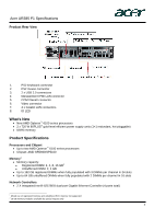
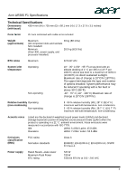
Acer AR385 F1 Specifications Expansion slots The primary I/O bus for the main board is PCIe Gen2. The following table lists the characteristics of the PCI-E bus segments. PCI express Bus Segment Characteristics of PCI Express Topology Expansion Slot # # of slots Type Bus Vol. Con. Location Length Width1 Width PCIe 3 PCIe Gen 2 x8 3.3V x16 Left Full height PCIe 1 PCIe Gen 2 x4 3.3V x4 Right Low profile PCIe 2 PCIe Gen 2 x2 3.3V x4 Right Low profile NOTE: 1. Indicates the number of physical electrical lanes running to a PCIe® connector. 2. Default bus assignment (in decimal). Inserting cards with PCI™ bridges may alter the actual bus assignment number. 3. Slots are enumerated differently based on the operating system. Microsoft® operating systems enumerate Device ID by bus starting from the lowest bus to the highest. Storage controller AMD® SP5100 SATA controller Integrated Serial ATA controller Simultaneous drive transfer channels 6 channels Transfer rate 3 Gb/s per channel synchronous (maximum theoretical) Data transfer method Non-RAID mode RAID mode (Adaptec® RAID driver) Drive support Serial ATA Data transfer modes Legacy mode Combined mode Protocol Serial ATA Feature NCQ (Native Command Queuing) AHCI (Advanced Host Controller Interface) RAID levels supported 0, 1, 10 RAID features Supports multiple logical volumes RAID OS support Supports setup through ROM based array configuration utility installation scripting NOTE: This controller requires the software RAID driver to support hot-plug functions. Windows Server® 2003 Windows Server® 2008 Windows Server® 2008 R2 Red Hat® Enterprise Linux 5.4 Novell® SuSE® Linux Enterprise Server 11 VMWare ESXi™ 4 VMWare ESX™ 4 7
-
 1
1 -
 2
2 -
 3
3 -
 4
4 -
 5
5 -
 6
6 -
 7
7 -
 8
8 -
 9
9 -
 10
10 -
 11
11 -
 12
12 -
13
-
14
-
15
-
16
-
17
-
18
-
19
-
20
 |
 |
