Acer AW2000ht-AW170ht F1 Acer AW2000ht w AW170htx F1 Server Service Guide
Acer AW2000ht-AW170ht F1 Manual
 |
View all Acer AW2000ht-AW170ht F1 manuals
Add to My Manuals
Save this manual to your list of manuals |
Acer AW2000ht-AW170ht F1 manual content summary:
- Acer AW2000ht-AW170ht F1 | Acer AW2000ht w AW170htx F1 Server Service Guide - Page 1
Acer AW2000ht Service Guide PART NO.: PRINTED IN TAIWAN - Acer AW2000ht-AW170ht F1 | Acer AW2000ht w AW170htx F1 Server Service Guide - Page 2
machines. Revision History Please refer to the table below for the updates made on Acer AW2000ht service guide. Date Chapter Updates Copyright Copyright © 2010 by Acer Inc. All rights reserved. No part of this publication may be reproduced, transmitted, transcribed, stored in a retrieval - Acer AW2000ht-AW170ht F1 | Acer AW2000ht w AW170htx F1 Server Service Guide - Page 3
information related to the current topic. Alerts you to any damage that might result from doing or not doing specific actions. Gives precautionary measures to avoid possible hardware or software problems. Reminds you to do specific actions relevant to the accomplishment of procedures. Chapter - Acer AW2000ht-AW170ht F1 | Acer AW2000ht w AW170htx F1 Server Service Guide - Page 4
them. CAUTION: Do not operate the server for long periods with the access panel open or removed. Operating the server in this manner results in improper airflow and improper cooling that can lead to thermal damage. Preventing electrostatic discharge To prevent damaging the system, be aware of the - Acer AW2000ht-AW170ht F1 | Acer AW2000ht w AW170htx F1 Server Service Guide - Page 5
Table of Contents Preface ii Safety, Care and Regulatory Information iv System components 1 System parts list 2 Removal and replacement procedures 7 Extend the server from the rack 8 Power down the server 10 Remove the server from the rack 11 System specifications 13 Hardware - Acer AW2000ht-AW170ht F1 | Acer AW2000ht w AW170htx F1 Server Service Guide - Page 6
Table of Contents System diagnositcs 63 System Check Procedures 63 AMI BIOS Recovery 64 BMC Event Troubleshooting 65 BIOS Setup 67 Main setup 68 Advanced Settings 69 Advanced Chipset Control 71 Security Settings 76 System Management Settings 77 Boot 79 Exit Options - Acer AW2000ht-AW170ht F1 | Acer AW2000ht w AW170htx F1 Server Service Guide - Page 7
components Chapter 1 Item 1 2 3 4 5 6 7 8 9 10 11 Description Cover olates Mainboards Memory modules CPUs CPU heatsinks Chassis Power supply Riser card brackets Adapter card supporting plates Add-on-card power adapter cards Riser card Item 12 13 14 15 16 17 18 19 20 21 22 Description Riser card - Acer AW2000ht-AW170ht F1 | Acer AW2000ht w AW170htx F1 Server Service Guide - Page 8
parts list Category ODM Description BOARD HOT-PLUG BACKPLANE BOARD 2U Twin HDD Backplane support Sup 6x3.5" SATA hdd; hot swap Acer PN TBC MAIN BOARD Acer GW170ht F1 Node Kit TBC Acer GW170htq F1 Node Kit TBC NETWORK CARD POWER DISTRIBUTION MODULE Intel® Gigabit ET Dual Port Server - Acer AW2000ht-AW170ht F1 | Acer AW2000ht w AW170htx F1 Server Service Guide - Page 9
.027 1400W 1U GOLD LEVEL PWS W/PM BUS PY.14M0S.001 CASE/COVER/BRACKET ASSEMBLY CHASSIS Acer OEM black SC827HD chassis w/o R1400W HS.R7900.001 AIR SHROUD 1U Air shound for AW2000ht/GW2000ht DUMMY NODE 3.5" HDD CARRIER SC827HD motherboard tray (Hot-swap, 2U height) 3.5" HDD CARRIER 3.5" HDD - Acer AW2000ht-AW170ht F1 | Acer AW2000ht w AW170htx F1 Server Service Guide - Page 10
, WD1002FBYS, 3Gb/s, 32MB 500GB, WD RE3 SATA2 7200RPM, WD5002ABYS, 3Gb/s, 32MB LEFT HANDLE WITH FRONT CONTROL PANEL 250GB, WD RE3 SATA2 7200RPM, WD2502ABYS, 3Gb/s, 32MB Acer PN KH.02K01.001 KH.02KW1.001 KH.01K01.012 KH.01KW1.012 KH.50001.016 KH.500W1.016 KH.01K08.007 KH.01KW8.007 - Acer AW2000ht-AW170ht F1 | Acer AW2000ht w AW170htx F1 Server Service Guide - Page 11
/s QPI, DDR3-1066, LGA1366, 40W, AT80614005484AA, SLBVD, B-1) Intel Xeon DP Quad-Core L5609(Westmere-EP, 1.86GHz, 12MB, 5.86GT/s QPI, DDR3-1066, LGA1366, 40W, AT80614005940AA, SLBVJ, B-1) Acer PN KC.50201.EP5 KC.502W1.EP5 KC.55301.EPL KC.553W1.EPL KC.55201.EPL KC.552W1.EPL KC.50601.EPL KC.506W1.EPL - Acer AW2000ht-AW170ht F1 | Acer AW2000ht w AW170htx F1 Server Service Guide - Page 12
/s SAS, black color, 2 x eSATA to SFF8088 cable (2m), NA/Asia/Europe power cables) Quantum ext. LTO-4 1U SAS rackmount NAME PLATE Acer SC827 (GW2000ht) Logo Mylar(Also included in chassis) Acer PN KN.1GB0B.032 KN.1GBWB.032 KN.2GB0B.016 KN.2GBWB.016 KN.4GB0B.008 KN.4GBWB.008 KN.8GB0B - Acer AW2000ht-AW170ht F1 | Acer AW2000ht w AW170htx F1 Server Service Guide - Page 13
following procedures: • Extend the server from the rack If you are performing service procedures in an Acer branded, telco, or third-party rack cabinet, you can use the locking feature of the rack rails to support the server and gain access to internal components. For more information about telco - Acer AW2000ht-AW170ht F1 | Acer AW2000ht w AW170htx F1 Server Service Guide - Page 14
Extend the server from the rack 1. If the server is screwed into the rack, remove the screws and set them aside. 8 Chapter 2 - Acer AW2000ht-AW170ht F1 | Acer AW2000ht w AW170htx F1 Server Service Guide - Page 15
2. Grasp the handles and extend the server from the rack. WARNING:To reduce the risk of personal injury or equipment damage, be sure that the rack is adequately stabilized before extending a component from the rack. 3. After performing the installation or maintenance procedure, slide the server - Acer AW2000ht-AW170ht F1 | Acer AW2000ht w AW170htx F1 Server Service Guide - Page 16
Power down the server WARNING: To reduce the risk of personal injury, electric shock, or damage to the equipment, remove the power cord to remove power from the server. The front panel Power On/Standby button does not completely shut off system power. Portions of the power supply and some internal - Acer AW2000ht-AW170ht F1 | Acer AW2000ht w AW170htx F1 Server Service Guide - Page 17
Remove the server from the rack To remove the server from the rack: 1. Power down the server. 2. Extend the server from the rack 3. Disconnect the cabling and remove the server from the rack. For more information, refer to the documentation that ships with the rack mounting option. 4. Place the - Acer AW2000ht-AW170ht F1 | Acer AW2000ht w AW170htx F1 Server Service Guide - Page 18
12 Chapter 2 - Acer AW2000ht-AW170ht F1 | Acer AW2000ht w AW170htx F1 Server Service Guide - Page 19
Chapter 3 System specifications Hardware specifications System unit Specifications Processor socket Processor support Core logic chipsets LAN controller Memory controller Storage controller VGA controller I/O subsystem Memory Media storage I/O ports Status LED indicators Thermal solution Value - Acer AW2000ht-AW170ht F1 | Acer AW2000ht w AW170htx F1 Server Service Guide - Page 20
Environmental specifications Specifications Temperature range Operating Non-operating Humidity (non-condensing) Operating Non-operating Value 10°C to 35°C (50°F to 95°F) at sea level with an altitude derating of 1.0°C per every 305 m (1.8°F per every 1000 ft) above sea level to a maximum of 3050 m - Acer AW2000ht-AW170ht F1 | Acer AW2000ht w AW170htx F1 Server Service Guide - Page 21
Mechanical specifications Specifications Value System board platform Proprietary System board dimensions Length Width 417 mm (16.4 in) 165 mm (6.5 in) Server dimensions Height Width Depth 2U 88 mm (3.47 in) 438 mm (17.25 in) 724 mm (28.5 in) Server weight Maximum (all processors, memory, - Acer AW2000ht-AW170ht F1 | Acer AW2000ht w AW170htx F1 Server Service Guide - Page 22
Power supply specifications Specifications Input voltage specifications Rated input voltage Input specifications Rated input line Frequency range Rated input power Rated input current BTU rating Steady state power BTU/hr Ambient temperature range Relative humidity (non-condensing) - Acer AW2000ht-AW170ht F1 | Acer AW2000ht w AW170htx F1 Server Service Guide - Page 23
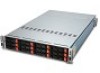
System appearance Front view Chapter 4 No. 1 2 3 4 5 6 7 8 9 10 11 Icon Component Power button/indicator LAN activity indicator Status/fault indicator System ID button/indicator Six 3.5-inch hot-plug drive bays (A0 to A5) for node A Six 3.5-inch hot-plug drive bays (B0 to B5) for node B Hot-plug - Acer AW2000ht-AW170ht F1 | Acer AW2000ht w AW170htx F1 Server Service Guide - Page 24
socket 6 Power supply modules 7 Power supply module handles 8 Server node A 9 System ID switch 10 InfiniBand port QSFP connector (only available for GW170htq F1) 11 Video port 12 Serial port 13 Gigabit LAN ports (RJ45) 14 USB 2.0 ports 15 Management port (RJ-45) 16 Server node - Acer AW2000ht-AW170ht F1 | Acer AW2000ht w AW170htx F1 Server Service Guide - Page 25
Internal components No. Component 1 Hard disk drives 2 System fan modules 3 Adapter board 4 Air duct bracket 5 PCIe riser board bracket assembly 6 Mainboard 7 Power supply module Chapter 4 19 - Acer AW2000ht-AW170ht F1 | Acer AW2000ht w AW170htx F1 Server Service Guide - Page 26
the : • Front panel • Hot-plug HDD carrier • Rear panel • LAN port Knowing what each LED indicator signifies can aid in problem diagnosis and troubleshooting. Front panel LED indicators LED indicator Power indicator Status/fault indicator LAN activity indicator System ID indicator LED color Green - Acer AW2000ht-AW170ht F1 | Acer AW2000ht w AW170htx F1 Server Service Guide - Page 27
Hard disk drive sequence and LED indicators The hard drive sequence is as follows: Bay no. Node A HDD A0 to A5 Node B HDD B0 to B5 Description Six 3.5-inch hot-plug drive bays controlled by node A Six 3.5-inch hot-plug drive bays controlled by node B Drive activity LED indicators are mounted on - Acer AW2000ht-AW170ht F1 | Acer AW2000ht w AW170htx F1 Server Service Guide - Page 28
System block diagram 22 Chapter 4 - Acer AW2000ht-AW170ht F1 | Acer AW2000ht w AW170htx F1 Server Service Guide - Page 29
using the power button on its own control panel. An additional power supply module may be added to provide redundant power. The GW170htq F1 includes an InfiniBand port at QDR (quad data rate) speed. InfiniBand is a scalable serial communications link intended for connecting processors with high - Acer AW2000ht-AW170ht F1 | Acer AW2000ht w AW170htx F1 Server Service Guide - Page 30
Mainboard connectors 24 Chapter 5 - Acer AW2000ht-AW170ht F1 | Acer AW2000ht w AW170htx F1 Server Service Guide - Page 31
PWR 20 CPU2 21 Slot 1 22 JNMI1 23 JWD Description System ID switch Alarm reset header InfiniBand connector QSFP connector (only available for GW170htq F1). Video port Internal speaker/buzzer header Serial port Gigabit LAN ports (RJ45) Universal Serial Bus (USB) ports 0/1 Management port (RJ45) LAN1 - Acer AW2000ht-AW170ht F1 | Acer AW2000ht w AW170htx F1 Server Service Guide - Page 32
Mainboard jumpers No. Jumper Description Default Setting 1 JWD Enable/Disable/ Pins 1-2 (Reset) Reset Watch Dog 2 JBT1 Clear CMOS Instead of pins, this jumper consists of contact pads to prevent accidental clearing of the CMOS contents. To clear CMOS, disconnect the power and short the CMOS - Acer AW2000ht-AW170ht F1 | Acer AW2000ht w AW170htx F1 Server Service Guide - Page 33
1 LE4 System ID LED indicator (rear) 2 LEB1 InfiniBand link LED indicator (only available for GW170htq F1) 3 LEB2 InfiniBand activity LED indicator (only available for GW170htq F1) 4 LE2 BMC Heartbeat LED Indicator 5 LE3 HDD/SATA LED Indicator 6 LE1 Onboard standby PWR warning - Acer AW2000ht-AW170ht F1 | Acer AW2000ht w AW170htx F1 Server Service Guide - Page 34
28 Chapter 5 - Acer AW2000ht-AW170ht F1 | Acer AW2000ht w AW170htx F1 Server Service Guide - Page 35
step-by-step procedures on how to disassemble the server SATA backplane board for maintenance and troubleshooting. To disassemble the server, please pay attention to each section's instruction and tools needed. NOTE: The screws for the different components vary in size. During the disassembly - Acer AW2000ht-AW170ht F1 | Acer AW2000ht w AW170htx F1 Server Service Guide - Page 36
only. Open: Default, multiple power button functionality Closed: Single power button functionality Open: Default Closed: LED test setting Front indicators JP57 1 + FAN4 4 F16 C269 C203 + C200 + 16 JF6 JF6-B No. 1 2 LED D11 D1 Y2 U21 32 33 48 49 1 FAN3 4 JP56 JP71 UPGRADE#B C201 + C198 - Acer AW2000ht-AW170ht F1 | Acer AW2000ht w AW170htx F1 Server Service Guide - Page 37
31 C A C A D28 D33 ACT#B5 R245 R177 FAIL#B5 C D27 ACT#B3 C A A D32 R176 R100FAIL#B3 C D26 ACT#B1 A C A R175 D31 R465FAIL#B1 SAS J20 #B5 J19 SAS #B3 J18 SAS #B1 C120 R248 R173 R244 R164 R101 J17 SAS #B4 J15 SAS #B2 J13 SAS #B0 HDD No. SATA HDD A0 SATA HDD A2 SATA HDD A4 SATA HDD - Acer AW2000ht-AW170ht F1 | Acer AW2000ht w AW170htx F1 Server Service Guide - Page 38
C D28 ACT#B5 C A A D33 R245 R177 FAIL#B5 C D27 ACT#B3 C A A D32 R176 R100FAIL#B3 C D26 ACT#B1 A C R175 D31 R465FAIL#B1 A Rear indicators 54 1 53 2 C87 R162 29 26 28 62 27 55 59 58 R154 R149 R130 U47 C94 R153 R138 R152 R111 R184 R147 J3 SAS #A4 J2 SAS #A2 SAS827HD - Acer AW2000ht-AW170ht F1 | Acer AW2000ht w AW170htx F1 Server Service Guide - Page 39
chapter contains step-by-step procedures on how to disassemble the server system for maintenance and troubleshooting. To disassemble the server, please pay attention to each section's instruction and tools needed. NOTE: The screws for the different components vary in size. During the disassembly - Acer AW2000ht-AW170ht F1 | Acer AW2000ht w AW170htx F1 Server Service Guide - Page 40
Hard disk drive removal and installation The system has four drive bays. Follow these steps: 1. Remove the hard disk drive carrier. a. Unlock ( ) the HDD carrier latch. b. Slide the HDD carrier latch ( ) to release the lever. c. Pull the lever and slide the carrier ( ) from the chassis. 2. Replace - Acer AW2000ht-AW170ht F1 | Acer AW2000ht w AW170htx F1 Server Service Guide - Page 41
b. Install a new hard disk drive ( ) into the carrier and secure it with four screws ( ) . 3. Install the hard disk drive carrier. a. Slide the HDD carrier all the way ( ) into the drive bay. b. Use the lever to push the HDD carrier ( ) until it locks into place; then close the HDD carrier lever. c. - Acer AW2000ht-AW170ht F1 | Acer AW2000ht w AW170htx F1 Server Service Guide - Page 42
Power supply removal and installation The system uses a single 1200W/1400W power supply module which operates at 100 to 140/180 to 240V. You can install a second power module for hot-plug and redundancy. Follow these steps: 1. Power down the server and unplug the power cord. 2. Remove the power - Acer AW2000ht-AW170ht F1 | Acer AW2000ht w AW170htx F1 Server Service Guide - Page 43
Top cover removal and installation Removing the top cover Follow these steps: 1. Remove the two screws ( ) securing the cover to the chassis. 2. Lift the cover ( ) off the chassis. 3. Put the top cover aside for reinstallation later. Installing the top cover 1. Align the top cover tabs with the - Acer AW2000ht-AW170ht F1 | Acer AW2000ht w AW170htx F1 Server Service Guide - Page 44
running to determine which of the fans has failed. 2. Remove the fan module. a. Disconnect the fan cable ( ) . b. Release the fan cable ( ) from the cable guide. c. Pull up the fan module ( ) and detach it from the fan holder. Installing the fan module 1. Insert the new fan module ( ) into the fan - Acer AW2000ht-AW170ht F1 | Acer AW2000ht w AW170htx F1 Server Service Guide - Page 45
3. Push the fan cable ( ) through the cable guide. 4 Install the top cover. NOTE: Check the routing of the cables when connecting the cable. Hardware removal and installation 39 - Acer AW2000ht-AW170ht F1 | Acer AW2000ht w AW170htx F1 Server Service Guide - Page 46
Fan holder removal and installation Removing the fan holder 1. Remove the fan modules, see "Removing the fan module" on page 38). 2. Remove the four screws ( ) that secure the fan holder to the system chassis. 3. Pull up the fan holder ( ) and detach from the system chassis. 4. Repeat steps 2 and 3 - Acer AW2000ht-AW170ht F1 | Acer AW2000ht w AW170htx F1 Server Service Guide - Page 47
Replacing a server node If you need to replace a server node module, follow these steps: 1. Turn off the power to the node module. 2. Press the tabs ( ) on both sides and use the handles ( ) to pull out and remove the node module. 3. Insert a new node module into the vacated server node bay. - Acer AW2000ht-AW170ht F1 | Acer AW2000ht w AW170htx F1 Server Service Guide - Page 48
The system has two preinstalled riser cards (one card for each node) designed specifically for use in the 2U rackmount chassis. Each riser card supports full-height, full-length PCI Express x8 cards. Perform the following steps to install an add-on card: Installing a PCI Express card 1. Remove the - Acer AW2000ht-AW170ht F1 | Acer AW2000ht w AW170htx F1 Server Service Guide - Page 49
Replacing the riser card module Follow these steps: 1. Remove the server node (see "Replacing a server node" on page 41). 2. Remove any installed PCI Express card. See "PCI Express card removal and installation" on page 42. 3. Remove the five screws that attach the riser card module to the server - Acer AW2000ht-AW170ht F1 | Acer AW2000ht w AW170htx F1 Server Service Guide - Page 50
Removing the power adapter card 1. Remove the two screws ( ) that secure the mainboard tray supporting brackets to the power adapter card. 2. Detach the mainboard tray supporting brackets ( ). 3. Remove the four screws ( ) that secure the power adapter card to the riser card brackets. 4. Detach the - Acer AW2000ht-AW170ht F1 | Acer AW2000ht w AW170htx F1 Server Service Guide - Page 51
Removing and installing the cover plate Removing the cover plate 1. Remove the server node (see "Replacing a server node" on page 41). 2. Remove the four screws ( ) that secure the cover plate to the server node. 3. Lift the cover plate ( ) from the server node. Installing the cover plate 1. - Acer AW2000ht-AW170ht F1 | Acer AW2000ht w AW170htx F1 Server Service Guide - Page 52
Air shroud removal and installation Removing the air shroud You need to remove the air shroud to perform the following procedures: CAUTION: Always operate your server with the air shroud installed to ensure reliable and continued operation. Follow these steps: 1. Remove the cover plate (see " - Acer AW2000ht-AW170ht F1 | Acer AW2000ht w AW170htx F1 Server Service Guide - Page 53
Heatsink removal and installation Follow these steps: 1. Power down the server and unplug the power cord. 2. Remove the air shroud (see "Removing the air shroud" on page 44). 3. Using a screwdriver, loosen the heatsink screws from the mainboard. 4. Lift the heat sink away from the processor. 5. - Acer AW2000ht-AW170ht F1 | Acer AW2000ht w AW170htx F1 Server Service Guide - Page 54
4. Place the heatsink on top of the CPU so that the four mounting holes are aligned with those on the (preinstalled) heatsink retention mechanism. 5. Screw in two diagonal screws (i.e. the #1 and the #2 screws) until just snug. Do not fully tighten the screws or you may damage the CPU.) 6. Add the - Acer AW2000ht-AW170ht F1 | Acer AW2000ht w AW170htx F1 Server Service Guide - Page 55
CPU removal and installation The mainboard has two LGA 1366 processor sockets supporting dual-core or quad-core Intel Xeon processors. You have the option to upgrade the default processor or install a second one for a dual-processor configuration. - Acer AW2000ht-AW170ht F1 | Acer AW2000ht w AW170htx F1 Server Service Guide - Page 56
a. Hold the processor by its edges. Make sure the alignment tabs on the socket fit the notch ( ) located on the edge of the processor. The pins are keyed in such a way that you cannot install the processor in the wrong orientation without bending the pins. b. Insert the new processor ( ) in the - Acer AW2000ht-AW170ht F1 | Acer AW2000ht w AW170htx F1 Server Service Guide - Page 57
, 2A, 3A in blue) and B (PxDIMM1B, 2B, 3B in black). So, the system has a total of twelve memory slots. The memory slots support DDR3-1333 registered/unbuffered ECC memory modules. The folllowing illustration shows the processor 1 memory slots ( ) and processor 2 memory slots ( ). Independent mode - Acer AW2000ht-AW170ht F1 | Acer AW2000ht w AW170htx F1 Server Service Guide - Page 58
NA NA X X NA NA X X X X NA NA X X X X NA NA Notes: 1. Place DIMMs in "X" location. 2. DIMM population must correspond to the above tables. 3. DIMM modules support 1 GB, 2 GB, 4 GB and 8 GB DIMMS. 4. The size of each DIMM must be the same across the configuration. 5. Do not mix UDIMMs with - Acer AW2000ht-AW170ht F1 | Acer AW2000ht w AW170htx F1 Server Service Guide - Page 59
, 4 GB and 8 GB DIMMS. 4. The size of each DIMM must be the same across the configuration. 5. Do not mix UDIMMs with RDIMMs. Sparing mode (only supported on Intel Xeon Processor 5600 Series CPUs) • In this mode, if the system detects degrading memory and did not crash, the data in the failed - Acer AW2000ht-AW170ht F1 | Acer AW2000ht w AW170htx F1 Server Service Guide - Page 60
= Single Rank 2R = Dual Rank 4R = Quad Rank Note: If quad rank DIMM is used, a maximum of only two DIMMs per channel can be supported. This platform supports x4 and x8. Note: It is not recommend to mix DIMMs with different bit organizations in one system. PC3 - 6400 => DDR3- 800 PC3 - 8500 - Acer AW2000ht-AW170ht F1 | Acer AW2000ht w AW170htx F1 Server Service Guide - Page 61
4. Install the memory module. a. Align then insert the DIMM ( ) into the socket. b. Push down the DIMM ( )to the socket until the retaining clips snap inward. NOTE: The DIMM slot is slotted to ensure proper installation. If you insert a DIMM but it does not fit easily into the socket, you may have - Acer AW2000ht-AW170ht F1 | Acer AW2000ht w AW170htx F1 Server Service Guide - Page 62
Mainboard removal and installation To remove the mainboard, follow these steps: 1. Power down the server and unplug the power cord. 2. Remove the server node (see "Replacing a server node" on page 41). 3. Remove all installed PCI Express cards (see "PCI Express card removal and installation" on page - Acer AW2000ht-AW170ht F1 | Acer AW2000ht w AW170htx F1 Server Service Guide - Page 63
12. The adapter card supporting plate ( ) detaches from the SATA board. Detach the SATA board ( ) from the mainboard. To install a mainboard, reverse the steps above. Hardware removal and installation 57 - Acer AW2000ht-AW170ht F1 | Acer AW2000ht w AW170htx F1 Server Service Guide - Page 64
Battery removal and installation Follow these steps: 1. Power down the server and unplug the power cord. 2. Remove the air shroud (see "Removing the air shroud" on page 46). 3. Locate the coin battery on the mainboard. 4. Remove the coin battery and replace it with a new one of the same type. 58 - Acer AW2000ht-AW170ht F1 | Acer AW2000ht w AW170htx F1 Server Service Guide - Page 65
Rackmount installation procedure CAUTION: To minimize the chances of injuries, make sure that two or more people help in installing the server. Follow these steps to install the system into a four-post rack: 1. Confirm that the left and right inner rails have been correctly identified. 2. Remove the - Acer AW2000ht-AW170ht F1 | Acer AW2000ht w AW170htx F1 Server Service Guide - Page 66
of two holes with closer spacing to the center of the next pair is equivalent to 1U. NOTE: The unit of measurement used in this guide is "U" (1U = 1.75 inches or 44.45 mm). The total sum of the heights of all components in the rack measured in "U" cannot exceed the - Acer AW2000ht-AW170ht F1 | Acer AW2000ht w AW170htx F1 Server Service Guide - Page 67
6. Pull out the server mounting rails from the left and right mounting rails. CAUTION: To avoid personal injury, care should be taken when pressing the inner rail release latches and sliding the component into the rack. 7. Install the server into the rack. a. Insert the inner rails into the server - Acer AW2000ht-AW170ht F1 | Acer AW2000ht w AW170htx F1 Server Service Guide - Page 68
b. Press the release latch ( ) and continue to push the server ( ) into the rack until you hear a click sound 8. For security purposes, tighten the right and left thumbscrews on the front panel to secure the server to the front of the rack as illustrated below. 62 Chapter 7 - Acer AW2000ht-AW170ht F1 | Acer AW2000ht w AW170htx F1 Server Service Guide - Page 69
contact that could short out power. 4. If the problem is not evident, continue with System Internal Inspection. System surface. 6. Remove the system cover. For instructions on removing system cover, refer to disassembling all components are Acer-qualified and supported. 10. Replace the system cover. - Acer AW2000ht-AW170ht F1 | Acer AW2000ht w AW170htx F1 Server Service Guide - Page 70
the recovery image and starts the BIOS recovery flash operation. When the flash operation completes, the system will reboot automatically. The system will show the result of the recovery process once it completes. 64 Chapter 8 - Acer AW2000ht-AW170ht F1 | Acer AW2000ht w AW170htx F1 Server Service Guide - Page 71
ID String Sensor Type Troubleshooting FAN # (FAN 1, FAN 2, ...) 0x04 The FAN # speed is too slow, occurs, please replace power supply. System on board power regulator voltage abnormal. Please call service help. +5VSB 0x02 5VSB of power supply is abnormal. Please check the power connector - Acer AW2000ht-AW170ht F1 | Acer AW2000ht w AW170htx F1 Server Service Guide - Page 72
66 Chapter 8 - Acer AW2000ht-AW170ht F1 | Acer AW2000ht w AW170htx F1 Server Service Guide - Page 73
. Each main BIOS menu option is described in this manual. The Main BIOS setup menu screen has two main NOTE: The BIOS has default text messages built in. Acer retains the option to include, omit or change any of the setup navigation process. These keys include , , , and arrow - Acer AW2000ht-AW170ht F1 | Acer AW2000ht w AW170htx F1 Server Service Guide - Page 74
Main setup When you first enter the BIOS setup utility, you will enter the main setup screen. You can always return to the main setup screen by selecting the main tab on the top of the screen. The main BIOS setup screen is shown below. System Overview System Time/System Date Use this option to - Acer AW2000ht-AW170ht F1 | Acer AW2000ht w AW170htx F1 Server Service Guide - Page 75
Power-on state for Numlock key. Wait For 'F1' If Error: Forces the system to wait until the key is pressed if an error occurs. supported by the processor and/or operating system. Hardware Prefetcher: If set to Enabled, the hardware prefetcher will prefetch streams of data and instructions - Acer AW2000ht-AW170ht F1 | Acer AW2000ht w AW170htx F1 Server Service Guide - Page 76
during an attack. IMPORTANT:The following feature is only available if supported by the processor and/or operating system. Simultaneous Multi-Threading: Set to Enabled to use simultaneous multi-threading technology, which will result in increased CPU performance. Intel EIST Technology: EIST (Enhanced - Acer AW2000ht-AW170ht F1 | Acer AW2000ht w AW170htx F1 Server Service Guide - Page 77
Advanced Chipset Control The items included in the Advanced Settings submenu are listed below: CPU Bridge configuration QPI Links Speed: This feature selects QPI data transfer speed. IMPORTANT:The following feature is only available when QPI Links Speed is set to Full Speed. QPI Frequency: This - Acer AW2000ht-AW170ht F1 | Acer AW2000ht w AW170htx F1 Server Service Guide - Page 78
the coalesce feature. Please refer to your add-on card user guide for the desired setting. South Bridge configuration This feature allows you to not, contact your manufacturer or install an ATA/133 IDE controller card that supports 48-bit LBA mode. • Block (Multi-Sector Transfer) - Block Mode - Acer AW2000ht-AW170ht F1 | Acer AW2000ht w AW170htx F1 Server Service Guide - Page 79
DMA Mode Description Automatically detect IDE DMA mode when the IDE disk drive support cannot be determined. Use Single Word DMA mode 0. It has a data is not required for system boot if your system has an oerating system that supports Plug & Play.) Select No to allow the BIOS to configure all devices - Acer AW2000ht-AW170ht F1 | Acer AW2000ht w AW170htx F1 Server Service Guide - Page 80
CPU can now send information to the motherboard what its Temperature Tolerance is, and not the other way around. This results in better CPU thermal management. Acer has leveraged this feature by assigning a temperature status to certain thermal conditions in the processor (Low, Medium and High - Acer AW2000ht-AW170ht F1 | Acer AW2000ht w AW170htx F1 Server Service Guide - Page 81
, chassis ventilation and room temperature to correct any problems. NOTE: The system may shut down if it website for further explanation: http://www.acpi.info/. ACPI APIC Support: Select Enabled to include the ACPI APIC Table Pointer in the , such as an x86 RDTSC Instruction embedded in the CPU. The - Acer AW2000ht-AW170ht F1 | Acer AW2000ht w AW170htx F1 Server Service Guide - Page 82
Security Settings The BIOS provides a Supervisor and a User password. If you use both passwords, the Supervisor password must be set first. Supervisor Password: This item indicates if a supervisor password has been entered for the system. Clear means such a password has not been used and Set means a - Acer AW2000ht-AW170ht F1 | Acer AW2000ht w AW170htx F1 Server Service Guide - Page 83
MAC Address/IP Address pairs that are manually entered (such as by a network administrator not exceed 255. Acer Address: The BIOS will automatically display the Acer address of this machine Remote Access: This allows you to enable Remote Access support. If Remote Access is set to Enabled, the - Acer AW2000ht-AW170ht F1 | Acer AW2000ht w AW170htx F1 Server Service Guide - Page 84
: Select Enabled to enable VT-UTF8 Combination Key support for ANSI/ VT100 terminals. Sredir Memory Display Delay: Defines the length of time in seconds to display memory information. Event Log Configuration View Event Log: - Acer AW2000ht-AW170ht F1 | Acer AW2000ht w AW170htx F1 Server Service Guide - Page 85
Boot This submenu allows you to configure boot settings for the system. Boot Device Priority This feature allows you to specify the sequence of priority for the Boot Device. • 1st Boot Device • 2nd Boot Device • 3rd Boot Device Hard Disk Drives This feature allows you to specify the boot sequence - Acer AW2000ht-AW170ht F1 | Acer AW2000ht w AW170htx F1 Server Service Guide - Page 86
Exit Options Select the Exit tab from the BIOS Setup Utility screen to enter the Exit BIOS Setup screen. Save Changes and Exit: When you have completed the system configuration changes, select this option to leave the BIOS Setup Utility and reboot the computer, so the new system configuration - Acer AW2000ht-AW170ht F1 | Acer AW2000ht w AW170htx F1 Server Service Guide - Page 87
Chapter 10 BIOS Beep Codes During POST (Power-On Self-Test) routines, which are performed each time the system is powered on, errors may occur. Non-fatal errors are those, which, in most cases, allow the system to continue the boot-up process. The error messages normally appear on the screen. Fatal - Acer AW2000ht-AW170ht F1 | Acer AW2000ht w AW170htx F1 Server Service Guide - Page 88
Troubleshooting POST BIOS beep codes Number of Beeps 1, 3 6, 7 8 Description Reseat the memory, or replace with known good modules. Fatal error indicating a serious problem expansion cards are absent, consult your system manufacturer's technical support. • If beep codes are not generated when all - Acer AW2000ht-AW170ht F1 | Acer AW2000ht w AW170htx F1 Server Service Guide - Page 89
Chapter 10 83 - Acer AW2000ht-AW170ht F1 | Acer AW2000ht w AW170htx F1 Server Service Guide - Page 90
84 Chapter 10 - Acer AW2000ht-AW170ht F1 | Acer AW2000ht w AW170htx F1 Server Service Guide - Page 91
BIOS POST Error Messages List Information unavailable. Chapter 11 Chapter 11 85 - Acer AW2000ht-AW170ht F1 | Acer AW2000ht w AW170htx F1 Server Service Guide - Page 92
86 Chapter 11