Acer AW2000ht-AW170ht F1 Acer AW2000ht w AW170htx F1 Server Service Guide - Page 36
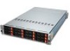
Front view, Front connectors and jumpers, Front indicators - f16
 |
View all Acer AW2000ht-AW170ht F1 manuals
Add to My Manuals
Save this manual to your list of manuals |
Page 36 highlights
Front view Front connectors and jumpers + + JP57 1 + FAN4 4 F16 C269 C203 + C200 + 16 JF6 JF6-B Y2 U21 32 33 48 49 1 FAN3 4 JP56 JP71 UPGRADE#B C201 + C198 R132 R128+ C197 C121 54 53 2 1 JF4 28 27 62 55 F23 F24 F25 59 58 F26 54 1 53 2 JPW1 12 SPI JP69 X1 JF3 MB-B 28 27 62 55 59 58 1 F36 13 D1 HB A C 44 34 11 23 4 12 U6 22 + J21 1 DEBUG SAS827HD REV 1.00 DESIGNED IN USA 1 JP55 FAN2 4 + C3 JP36: OPEN:DEFAULT CLOSE:ANY POWER BUTTON JP36 1 JP35: OPEN:DEFAULT JP35 CLOSE:LED TEST 1 C119 5 JPI2C1 TO PS C44 + 1 C45 + C85 + + C84 FAN1 1 JP54 48 33 49 54 1 53 2 64 16 8 JF2 JP70 5 UPGRADE#A 28 27 62 55 16 4 JPW3 59 58 JF5 JF5-A 54 53 2 1 1 BAR CODE 8 4 JPW2 MB-A JF1 5 28 27 62 55 1 59 58 No. 1 2 3 4 5 6 7 8 9 10 11 12 13 14 15 Connector Description JPI2C1 Power supply connector JP54 JP55 JP56 JP57 JF5-A Chassis fan 1 connector Chassis fan 2 connector Chassis fan 3 connector Chassis fan 4 connector Backplane to front panel connector JF6-B Backplane to front panel connector JPW1 JPW2 JPW3 JP70 JP70 JP69 JP36 Main power connector Secondary power connector Secondary power connector Upgrade connectors SPI connector Power button settings JP35 LED Test Function Provides power to the SMBUS and power control signals. Supply power to the chassis cooling fans. Connect the backplane to the front LED panels on the chassis. Connect the backplane to the front LED panels on the chassis. Provide power to the two nodes in the chassis. For manufacturing purposes only. Open: Default, multiple power button functionality Closed: Single power button functionality Open: Default Closed: LED test setting Front indicators JP57 1 + FAN4 4 F16 C269 C203 + C200 + 16 JF6 JF6-B No. 1 2 LED D11 D1 Y2 U21 32 33 48 49 1 FAN3 4 JP56 JP71 UPGRADE#B C201 + C198 R132 R128+ C197 C121 ON Blinking State 54 53 2 1 JF4 28 27 62 55 F23 F24 F25 59 58 F26 54 1 53 2 JPW1 12 SPI JP69 X1 JF3 MB-B 28 27 62 55 59 58 1 F36 13 D1 HB A C 44 34 11 23 4 12 U6 22 + J21 1 DEBUG SAS827HD REV 1.00 DESIGNED IN USA 1 JP55 FAN2 4 + C3 JP36: OPEN:DEFAULT CLOSE:ANY POWER BUTTON JP36 1 JP35: OPEN:DEFAULT JP35 CLOSE:LED TEST 1 C119 5 JPI2C1 TO PS C44 + 1 C45 + C85 + + C84 FAN1 1 JP54 48 33 49 54 1 53 2 64 16 8 JF2 JP70 5 UPGRADE#A 28 27 62 55 16 4 JPW3 59 58 JF5 JF5-A 54 53 2 1 1 BAR CODE 8 4 JPW2 MB-A JF1 5 28 27 62 55 1 59 58 Specification Indicates an overheat condition Indicates backplane activity 30 Chapter 3