Acer CB240HYK User Manual - Page 18
Connector pin assignment
 |
View all Acer CB240HYK manuals
Add to My Manuals
Save this manual to your list of manuals |
Page 18 highlights
English Connector pin assignment 19-pin color display signal cable 19 171513 11 9 7 5 3 1 18161412 10 8 6 4 2 PIN No. Description 1 TMDS Data2+ 3 TMDS Data2- 5 TMDS Data1 Shield 7 TMDS Data0+ 9 TMDS Data0- 11 TMDS Clock Shield 13 CEC 15 SCL 17 DDC/CEC Ground 19 Hot Plug Detect *only for certain models PIN No. Description 2 TMDS Data2 Shield 4 TMDS Data1+ 6 TMDS Data1- 8 TMDS Data0 Shield 10 TMDS Clock+ 12 TMDS Clock- 14 Reserved (N.C. on device) 16 SDA 18 +5V Power 19 171513 11 9 7 5 3 1 18161412 10 8 6 4 2 20-pin color MHL cable* PIN No. Description 7 MHL+ 18 VBUS 5 GND 17 GND *Only for MHL models PIN No. Description 9 MHL- 19 CBUS 11 GND 6
-
 1
1 -
2
-
3
-
4
-
5
-
6
-
7
-
8
-
9
-
10
-
11
-
12
-
 13
13 -
 14
14 -
 15
15 -
 16
16 -
 17
17 -
 18
18 -
 19
19 -
 20
20 -
 21
21 -
 22
22 -
 23
23 -
24
-
25
-
26
-
27
-
28
 |
 |
English
6
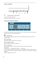
Connector pin assignment
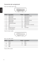
19-pin color display signal cable
PIN No.
Description
PIN No.
Description
1
TMDS Data2+
2
TMDS Data2 Shield
3
TMDS Data2-
4
TMDS Data1+
5
TMDS Data1 Shield
6
TMDS Data1-
7
TMDS Data0+
8
TMDS Data0 Shield
9
TMDS Data0-
10
TMDS Clock+
11
TMDS Clock Shield
12
TMDS Clock-
13
CEC
14
Reserved (N.C. on device)
15
SCL
16
SDA
17
DDC/CEC Ground
18
+5V Power
19
Hot Plug Detect
*only for certain models
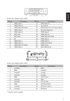
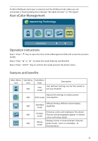
20-pin color MHL cable*
PIN No.
Description
PIN No.
Description
7
MHL+
9
MHL-
18
VBUS
19
CBUS
5
GND
11
GND
17
GND
*Only for MHL models
11
13
15
17
19
97531
2
64
8
10
1412
16
18
11
13
15
17
19
97531
2
64
8
10
1412
16
18