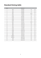
Acer EB321QUR User Manual - Page 16
Connector pin assignment
 |
View all Acer EB321QUR manuals
Add to My Manuals
Save this manual to your list of manuals |
Page 16 highlights
Connector pin assignment 19-pin color display signal cable PIN No. 1 2 3 4 5 6 7 8 9 10 Description TMDS data 2+ TMDS data 2 shield TMDS data 2TMDS data 1+ TMDS data 1 shield TMDS data 1TMDS data 0+ TMDS data 0 shield TMDS data 0TMDS clock+ PIN No. 11 12 13 14 15 16 17 18 19 Description TMDS clock shield TMDS clockCEC DDC-serial data SCL SDA DDC/CEC Ground +5V Power Hot Plug Detect 5
-
 1
1 -
2
-
3
-
4
-
5
-
6
-
7
-
8
-
9
-
10
-
 11
11 -
 12
12 -
 13
13 -
 14
14 -
 15
15 -
 16
16 -
 17
17 -
 18
18 -
 19
19 -
 20
20 -
 21
21 -
22
-
23
-
24
-
25
-
26
-
27
 |
 |
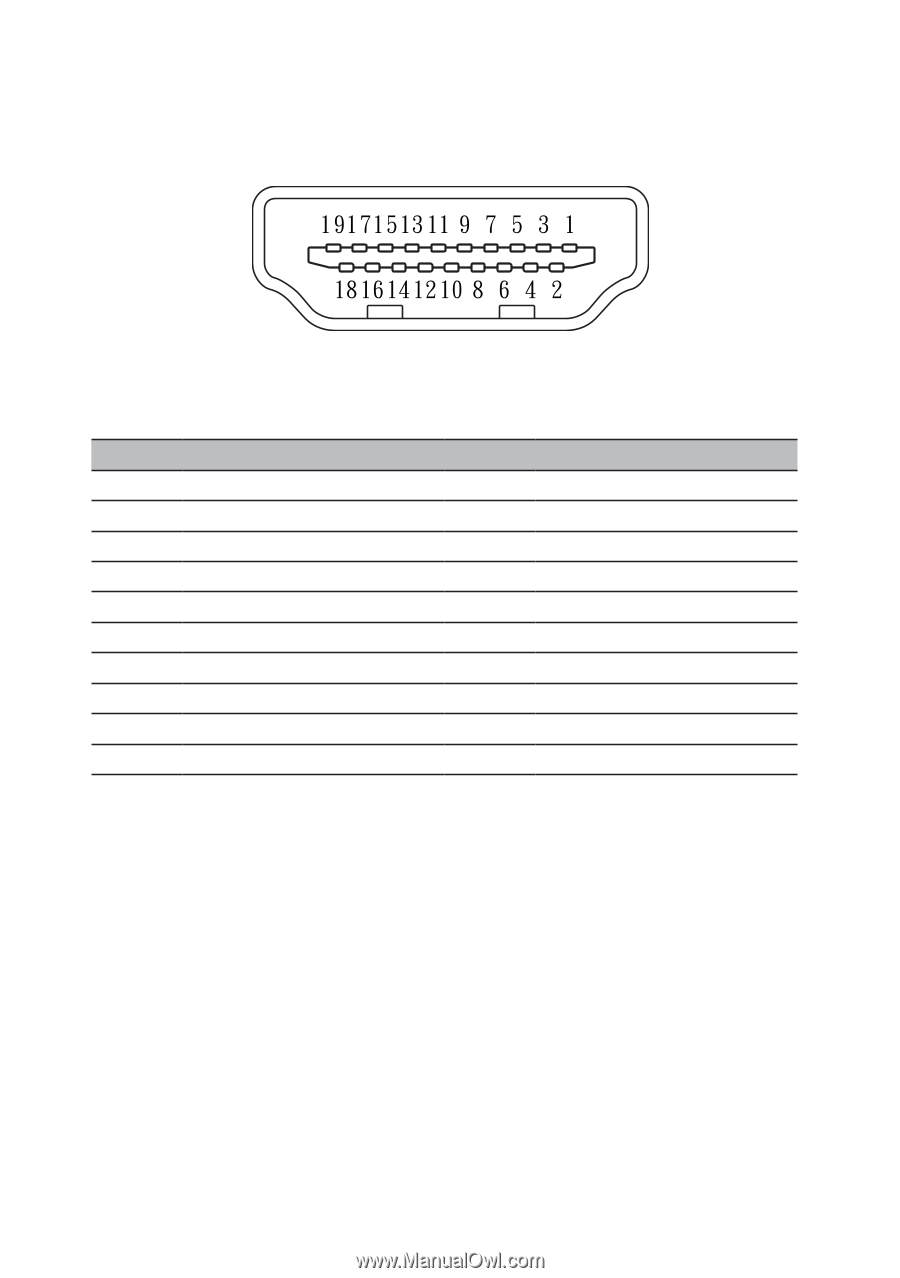
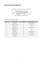
Connector pin assignment
19-pin color display signal cable
PIN No.
Description
PIN No.
Description
1
TMDS data 2+
11
TMDS clock shield
2
TMDS data 2 shield
12
TMDS clock-
3
TMDS data 2-
13
CEC
4
TMDS data 1+
14
DDC-serial data
5
TMDS data 1 shield
15
SCL
6
TMDS data 1-
16
SDA
7
TMDS data 0+
17
DDC/CEC Ground
8
TMDS data 0 shield
18
+5V Power
9
TMDS data 0-
19
Hot Plug Detect
10
TMDS clock+
5