Acer ED270R User Manual - Page 17
Connector pin assignment
 |
View all Acer ED270R manuals
Add to My Manuals
Save this manual to your list of manuals |
Page 17 highlights
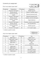
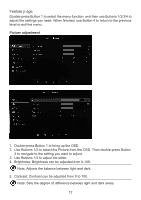
Connector pin assignment 20-pin color display signal cable* 19 17 15 13 11 9 7 5 3 1 20 18 16 14 12 10 8 6 4 2 Threading 1. 2. 3. 4. 5. 6. 7. 8. 9. 10. Explanations Channel 0 real signal Monitor ground Channel 0 auxiliary signal Channel 1 real signal Monitor ground Channel 1 auxiliary signal Channel 2 real signal Monitor ground Channel 2 auxiliary signal Channel 3 real signal Threading 11. 12. Explanations Monitor ground Channel 3 auxiliary signal 13. Reserved (protocol pull) 14. Reserved (protocol pull) 15. Auxiliary channel real signal 16. Signal detection 17. Auxiliary channel auxiliary signal 18. Hot plug detection 19. Monitor ground 20. 3.3 V power supply * Limited to specific models 19-pin color display signal cable* Threading 1. 2. 3. 4. Use TMDS data 2 + TMDS data 2 mask TMDS data 2 TMDS data 1 + 5. TMDS data 1 mask 6. TMDS data 1 - 7. TMDS data 0 + 8. TMDS data 0 mask 9. TMDS data 0 - Threading 10. 11. 12. 13. 14. 15. 16. 17. 18. 19. Use TMDS clock + TMDS clock mask TMDS clock - CEC Reserved (not connected on the device) SCL SDA DDC/CEC ground +5 V power supply Hot plug detection * Limited to specific models 7
-
 1
1 -
2
-
3
-
4
-
5
-
6
-
7
-
8
-
9
-
10
-
11
-
 12
12 -
 13
13 -
 14
14 -
 15
15 -
 16
16 -
 17
17 -
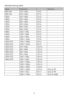 18
18 -
 19
19 -
 20
20 -
 21
21 -
 22
22 -
23
-
24
-
25
-
26
-
27
-
28
-
29
-
30
-
31
-
32
-
33
 |
 |
