Acer P215 User Manual - Page 10
Connector Pin Assignment
 |
View all Acer P215 manuals
Add to My Manuals
Save this manual to your list of manuals |
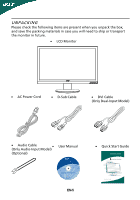
Page 10 highlights
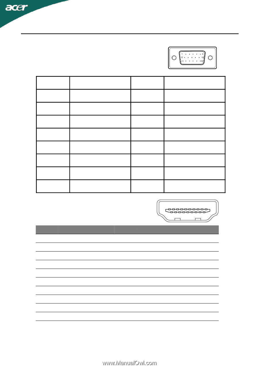
CONNECTOR PIN ASSIGNMENT 15-Pin Color Display Signal Cable PIN NO. 1. 2. 3. 4. 5. 6. 7. 8. DESCRIPTION Red Green Blue Monitor Ground DDC-return R-Ground G-Ground B-Ground PIN NO. 9. 10. 11. 12. 13. 14. 15. DESCRIPTION +5V Logic Ground Monitor Ground DDC-Serial Data H-Sync V-Sync DDC-Serial Clock 19-pin color display signal cable* 1917151311 9 7 5 3 1 1816141210 8 6 4 2 PIN No. Description 1 TMDS Data2+ 3 TMDS Data2- 5 TMDS Data1 Shield 7 TMDS Data0+ 9 TMDS Data0- 11 TMDS Clock Shield 13 CEC 15 SCL 17 DDC/CEC Ground 19 Hot Plug Detect PIN No. Description 2 TMDS Data2 Shield 4 TMDS Data1+ 6 TMDS Data1- 8 TMDS Data0 Shield 10 TMDS Clock+ 12 TMDS Clock- 14 Reserved (N.C. on device) 16 SDA 18 +5V Power * only for certain models EN-9
-
 1
1 -
2
-
3
-
4
-
 5
5 -
 6
6 -
 7
7 -
 8
8 -
 9
9 -
 10
10 -
 11
11 -
 12
12 -
 13
13 -
 14
14 -
 15
15 -
16
-
17
-
18
-
19
-
20
-
21
-
22
-
23
 |
 |
EN-9
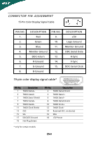
PIN NO.
DESCRIPTION
PIN NO.
DESCRIPTION
1.
Red
9.
+5V
2.
Green
10.
Logic Ground
3.
Blue
11.
Monitor Ground
4.
Monitor Ground
12.
DDC-Serial Data
5.
DDC-return
13.
H-Sync
6.
R-Ground
14.
V-Sync
7.
G-Ground
15.
DDC-Serial Clock
8.
B-Ground
CONNECTOR PIN ASSIGNMENT
15-Pin Color Display Signal Cable
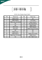
19-pin color display signal cable*
* only for certain models
PIN No.
Description
PIN No.
Description
1
TMDS Data2+
2
TMDS Data2 Shield
3
TMDS Data2–
4
TMDS Data1+
5
TMDS Data1 Shield
6
TMDS Data1–
7
TMDS Data0+
8
TMDS Data0 Shield
9
TMDS Data0–
10
TMDS Clock+
11
TMDS Clock Shield
12
TMDS Clock–
13
CEC
14
Reserved (N.C. on device)
15
SCL
16
SDA
17
DDC/CEC Ground
18
+5V Power
19
Hot Plug Detect
1
3
5
7
9
11
8
10
4
6
2
13
15
17
19
12
14
16
18