Acer TravelMate Spin P414RN-41 Lifecycle Extension Guide - Page 42
Mainboard Removal
 |
View all Acer TravelMate Spin P414RN-41 manuals
Add to My Manuals
Save this manual to your list of manuals |
Page 42 highlights
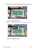
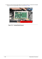
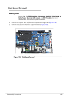
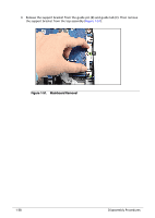
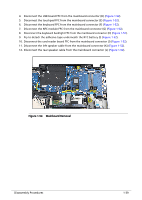
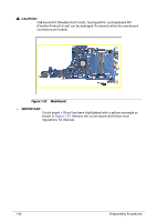
13. Remove four (4) screws securing the mainboard in place (Figure 1-53). Figure 1-53. Mainboard Removal 14. Release the mainboard from the guide pins (M) and its I/O ports from the I/O slots on the top assembly. Then carefully flip the mainboard t access the USB board FFC (Figure 1-54). M M Figure 1-54. Mainboard Removal 1-40 Disassembly Procedures
-
 1
1 -
2
-
3
-
4
-
5
-
6
-
7
-
8
-
9
-
10
-
11
-
12
-
13
-
14
-
15
-
16
-
17
-
18
-
19
-
20
-
21
-
22
-
23
-
24
-
25
-
26
-
27
-
28
-
29
-
30
-
31
-
32
-
33
-
34
-
35
-
36
-
 37
37 -
 38
38 -
 39
39 -
 40
40 -
 41
41 -
 42
42 -
 43
43 -
 44
44 -
 45
45 -
 46
46 -
 47
47 -
48
-
49
-
50
-
51
-
52
-
53
-
54
-
55
-
56
-
57
-
58
-
59
-
60
-
61
-
62
 |
 |

1-40
Disassembly Procedures
13.
Remove four (4) screws securing the mainboard in place (
Figure 1-53
).
Figure 1-53.
Mainboard Removal
14.
Release the mainboard from the guide pins (M) and its I/O ports from the I/O slots on
the top assembly. Then carefully flip the mainboard t access the USB board FFC
(
Figure 1-54
).
Figure 1-54.
Mainboard Removal
M
M