Adaptec AVA1515 Installation Guide - Page 4
Connecting Peripherals
 |
View all Adaptec AVA1515 manuals
Add to My Manuals
Save this manual to your list of manuals |
Page 4 highlights
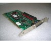
Inserting the Board WARNING: Turn OFF and disconnect the power to your computer and attached devices before you remove the chassis cover. See your computer's documentation for instructions on how to do this. 1 Remove the cover of your computer to expose the AT expansion slots. 2 Locate an unused AT expansion slot. AT-type slots have two edge connectors (one 62-pin and the other 34-pin) in line with each other. 3 Remove the expansion slot cover for this slot. 4 Align and insert the host adapter into the AT slot. Use the expansion slot cover screw to secure the host adapter to the frame. Note: Do not replace the chassis cover or reconnect the power yet! 5 Connecting Peripherals Setting SCSI IDs You must assign a different SCSI ID to each device on the AVA-1515 SCSI bus. See your SCSI peripheral documentation for directions on how to determine the ID and change it. s The default SCSI ID for AVA-1515 host adapters is SCSI ID 7. s We recommend that you assign SCSI IDs 0 and 1 to the first two SCSI hard disk drives in your PC. Connecting Cables SCSI devices are cabled together in a single, connected series called the SCSI bus. The SCSI bus cables must run sequentially from one device to the next. The host adapter is at the end of the SCSI bus if either the internal or the external SCSI connector is unused. The host adapter is in the middle of the bus if internal and external SCSI devices are installed. 3
-
 1
1 -
 2
2 -
 3
3 -
 4
4 -
 5
5 -
 6
6 -
 7
7 -
 8
8 -
 9
9 -
 10
10
 |
 |
