Akai MPK49 Operation Manual - Page 21
Control Change Parameters, Midi Channel Field, Control Change Field, Minimum Range Field
 |
View all Akai MPK49 manuals
Add to My Manuals
Save this manual to your list of manuals |
Page 21 highlights
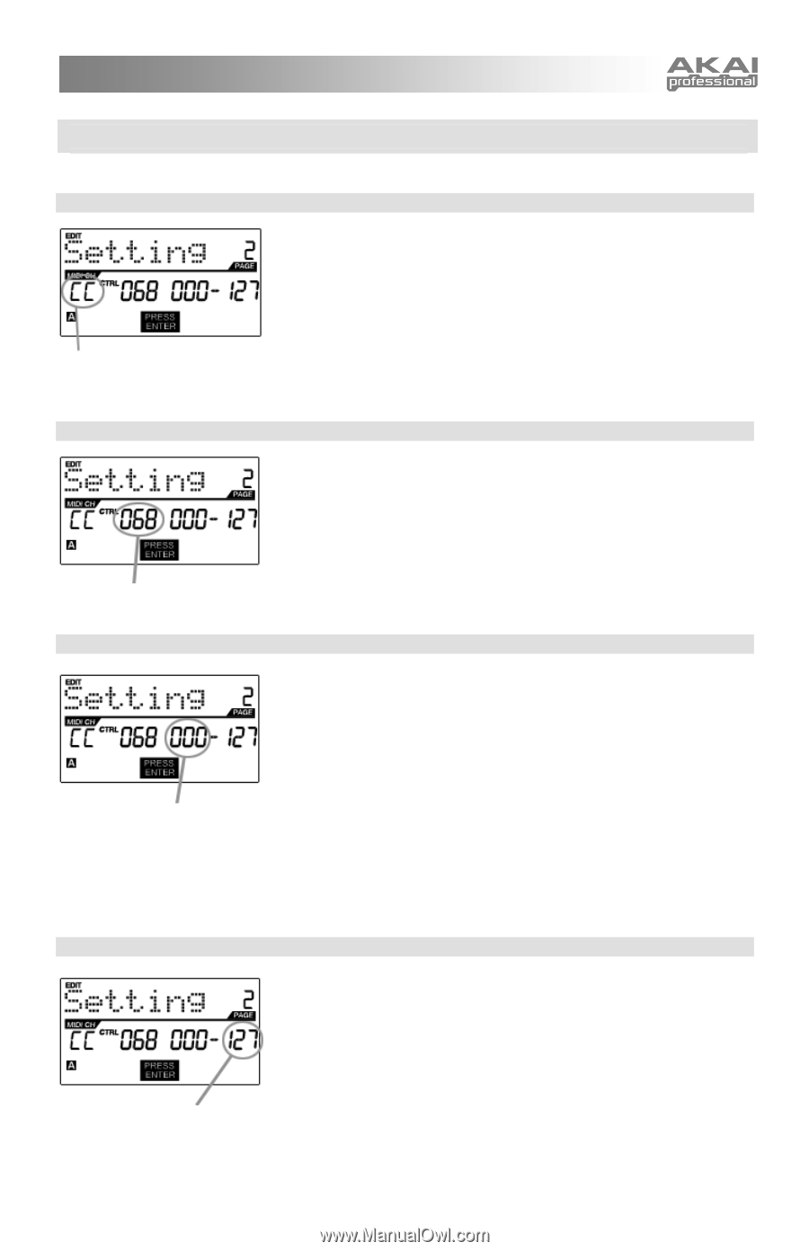
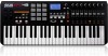
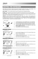
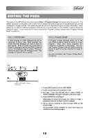
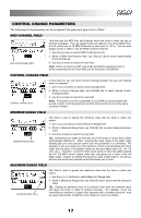
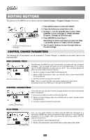
CONTROL CHANGE PARAMETERS The following list of parameters can be accessed if the pad event type is set to "Note". MIDI CHANNEL FIELD MIDI PORT/CHANNEL FIELD This field sets the MIDI Port and Channel which the knob or slider will use to transmit messages. You can assign knobs and sliders to one of two MIDI Ports, A or B, and to one of 16 MIDI Channels on each port (i.e. A14). You can also assign a knob or slider to use the MIDI Common Channel. 1. Use the [] button to select the next field. Note: When not used via USB, only knobs and sliders assigned to port A will be transmitted via the 5-pin MIDI port on the back of the MPK49. CONTROL CHANGE FIELD CONTROL CHANGE FIELD In this field you can set which Control Change Number the pad will transmit when it is pressed. 1. Use [] buttons to select Control Change field. 2. While in Control Change field, use [VALUE] dial to select desired Control Change Number. 3. Use the [>] button to select the next field. Note: To be able to control a parameter in your DAW or sound module with a knob or slider, both the parameter and the knob need to be set to the same Controller Number. MINIMUM RANGE FIELD MINIMUM RANGE FIELD This field is used to specify the minimum value that the knob or slider can output. 1. Use [] buttons to select Minimum Range field. 2. While in Minimum Range field, use [VALUE] dial to select desired minimum value. 3. Use the [>] button to select the next field. Tip: Sometimes you might not want the full 0-127 range of control that a slider automatically defaults to. Often, reducing the value range of the slider might actually give you more precise control over the parameter it is controlling. For example, if you are using one of the sliders to control a synced delay line, there might only be about 10 available values for the sync delay time (1/2, 1/4, 1/8 note, etc.). Therefore, it wouldn't make much sense to have the slider transmit the full 128 MIDI control values, since that only gives you a tenth of the full slider range. Instead, try setting the maximum value of that slider to 10 and you will see how much more precise control this allows you to have MAXIMUM RANGE FIELD MAXIMUM RANGE FIELD This field is used to specify the maximum value that the knob or slider can output. 1. Use the [] buttons to select Maximum Range field. 2. While in Maximum Range field, use [VALUE] dial to select desired maximum value. Tip: Setting the maximum value of a controller lower than the minimum value will cause the knob or slider to behave inversely. For example, if you are controlling an interface or plug-in that operates with a drawbar structure, such as organ instruments, it might be more intuitive to invert your sliders 17
-
 1
1 -
2
-
3
-
4
-
5
-
6
-
7
-
8
-
9
-
10
-
11
-
12
-
13
-
14
-
15
-
 16
16 -
 17
17 -
 18
18 -
 19
19 -
 20
20 -
 21
21 -
 22
22 -
 23
23 -
 24
24 -
 25
25 -
 26
26 -
27
-
28
-
29
-
30
-
31
-
32
-
33
-
34
-
35
-
36
-
37
-
38
-
39
-
40
-
41
-
42
-
43
 |
 |