Alesis MicroVerb4 User Manual
Alesis MicroVerb4 Manual
 |
View all Alesis MicroVerb4 manuals
Add to My Manuals
Save this manual to your list of manuals |
Alesis MicroVerb4 manual content summary:
- Alesis MicroVerb4 | User Manual - Page 1
ALESIS MicroVerb 4 Reference Manual - Alesis MicroVerb4 | User Manual - Page 2
Introduction Thank you for purchasing the Alesis MicroVerb 4 Multieffects Processor. To take full advantage of the MicroVerb 4's functions, and to enjoy long and trouble-free use, please read this user's manual carefully. How To Use This Manual This manual is divided into the following sections - Alesis MicroVerb4 | User Manual - Page 3
2 MicroVerb 4 Reference Manual - Alesis MicroVerb4 | User Manual - Page 4
CONTENTS Your First Session with the MicroVerb 4 7 Unpacking and Inspection ...7 Basic Connections ...7 Powering Up ...8 Setting Levels ...8 What's on the Front Panel 8 Auditioning Internal Programs 10 Switching Between Preset and User Banks 10 Adjusting Effects Mix Levels 10 Storing Edited - Alesis MicroVerb4 | User Manual - Page 5
...38 Realtime Modulation Functions 38 Troubleshooting 39 Trouble-Shooting Index ...39 Re-initializing ...39 Checking the Software Version 39 Maintenance/Service ...40 Cleaning...40 Obtaining Repair Service 40 MIDI Implementation Chart 42 Specifications ...43 4 MicroVerb 4 Reference Manual - Alesis MicroVerb4 | User Manual - Page 6
Contents MicroVerb 4 Reference Manual 5 - Alesis MicroVerb4 | User Manual - Page 7
6 MicroVerb 4 Reference Manual - Alesis MicroVerb4 | User Manual - Page 8
event that you need to return the MicroVerb 4 for servicing. The shipping carton should contain the following items: • This instruction manual • Alesis MicroVerb 4 with the same serial number as shown on shipping carton • AC Power Supply Adapter • Alesis warranty card 7 It is important to register - Alesis MicroVerb4 | User Manual - Page 9
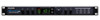
10 INPUT MIX OUTPUT DUAL CHANNEL PARALLEL PROCESSOR CLIP -6dB STORE -12dB -32dB L INPUT R 00-99 PRESET 100-199 USER BANK MIDI 45 7 9 The MicroVerb 4's Front Panel contains the following: ¨ Input. The Input level control sets the level going into the MicroVerb 4. This should be adjusted - Alesis MicroVerb4 | User Manual - Page 10
this button is clicked once, a Program in the opposite bank will be selected. (i.e. If Preset Program 34 is selected when Bank is pressed, the MicroVerb 4 will switch to User Program134.) If the [BANK/ MIDI] button is held for more than one second, the MIDI channel number will be displayed. You can - Alesis MicroVerb4 | User Manual - Page 11
back to User 199 but instead will remain at Preset 00. Adjusting Effects Mix Levels Whether a Program contains a single effect or two or three effects, you can adjust the MicroVerb 4's [MIX] control to obtain a desirable balance between the original, uneffected signal and each effect's output. The - Alesis MicroVerb4 | User Manual - Page 12
time you power on the unit if you haven't stored the edited Program into memory. If you select another Program from memory before storing the edited Program, your changes will also be lost. 7 Although the MicroVerb 4 has two banks (Preset and User), you can only store Programs in the User bank. To - Alesis MicroVerb4 | User Manual - Page 13
Chapter 1 - Your First Session with the MicroVerb 4 12 MicroVerb 4 Reference Manual - Alesis MicroVerb4 | User Manual - Page 14
end of the power adapter cord into MicroVerb 4's [POWER] socket and the male (plug) end into a source of AC power. It's good practice to not plug in the MicroVerb 4 until all other cables are hooked up. 7 Alesis cannot be responsible for problems caused by using the MicroVerb 4 or any associated - Alesis MicroVerb4 | User Manual - Page 15
/MONO] and [RIGHT] outputs can be connected to the inputs of a mixer/amplifier if stereo processing effects are desired. If using the effect sends of a mixer, you have the advantage of sending any of the mixer's input channels to the MicroVerb 4's input(s), and have control over the level of each - Alesis MicroVerb4 | User Manual - Page 16
two mixer inputs. INSTRUMENT OR EFFECTS SEND TO MIXING CONSOLE OR AMPLIFIER LEFT/MONO INPUT RIGHT INPUT LEFT OUTPUT INPUT MIX OUTPUT DUAL CHANNEL PARRELL PROCESSOR CLIP -6dB -12dB -32dB L INPUT R 00-99 PRESET 100-199 USER STORE BANK MIDI RIGHT OUTPUT MicroVerb 4 Reference Manual 15 - Alesis MicroVerb4 | User Manual - Page 17
signal mixed with it (since these two signals are blended together at the mixer). Therefore, it may be necessary to modify the mix so that only effected signal is present at the MicroVerb 4's outputs. To do this, turn the Mix control all the way to the right. 16 MicroVerb 4 Reference Manual - Alesis MicroVerb4 | User Manual - Page 18
mono cord from the [RIGHT] output of the MicroVerb 4 to an adjacent effect return or mixer input. AUX SEND 1 LEFT/MONO INPUT INPUT MIX OUTPUT DUAL CHANNEL PARRELL PROCESSOR CLIP -6dB -12dB -32dB L INPUT R 00-99 PRESET 100-199 USER STORE BANK MIDI LEFT OUTPUT RIGHT OUTPUT MIXER AUX - Alesis MicroVerb4 | User Manual - Page 19
LEFT/MONO INPUT INPUT MIX OUTPUT DUAL CHANNEL PARRELL PROCESSOR CLIP -6dB -12dB -32dB L INPUT R 00-99 PRESET 100-199 USER STORE BANK MIDI LEFT OUTPUT Using Main Outputs When you want to add effects to everything on the mixer, you can connect the MicroVerb 4 between the mixer's outputs and - Alesis MicroVerb4 | User Manual - Page 20
). LEFT MASTER OUT LEFT/MONO INPUT RIGHT MASTER OUT RIGHT INPUT INPUT MIX OUTPUT DUAL CHANNEL PARRELL PROCESSOR CLIP -6dB -12dB -32dB L INPUT R 00-99 PRESET 100-199 USER STORE BANK MIDI LEFT OUTPUT RIGHT OUTPUT MIXER LEFT INPUT RIGHT INPUT POWER AMP MicroVerb 4 Reference Manual 19 - Alesis MicroVerb4 | User Manual - Page 21
there are many opportunities for ground loop problems to occur. These show up as hums, sure that the audio wires don't run parallel to any AC wire (they should only cross control room monitor power amp. B) Plug in each tape machine and outboard effects device one at MicroVerb 4 Reference Manual - Alesis MicroVerb4 | User Manual - Page 22
Hosa (YPP-118). The footswitch connected to the tip of this jack will function as a Bypass pedal. The footswitch connected to the center ring of this jack will function as a Control pedal. (See below.) You may also use a dual footswitch, which has two pedals on one MicroVerb 4 Reference Manual 21 - Alesis MicroVerb4 | User Manual - Page 23
Control footswitch will have no effect. Tap From Audio. If the Control footswitch is held down and audio is played into the inputs, these impulses will be used to set the delay time. For example, hold down the Control footswitch on a delay program and play two staccato notes on a guitar, keyboard - Alesis MicroVerb4 | User Manual - Page 24
) on Acoustic Guitar, Piano, and Strings. Chorus/Flange Effects (Programs 30-49, 130-149) The Chorus and Flange effects alter the pitch and delay of a signal in various ways to produce "layered" timbres that are more complex than the original signal. Although MicroVerb 4 Reference Manual 23 - Alesis MicroVerb4 | User Manual - Page 25
SIGNAL LEFT CHORUSED OUTPUT RIGHT CHORUSED OUTPUT Quad Chorus Quad Chorus modulates four delayed signals, each with its phase offset by 90∞ . It gives you twice as much modulation effect as the Stereo Chorus, so it's great for really fattening up a sound. Chorus 24 MicroVerb 4 Reference Manual - Alesis MicroVerb4 | User Manual - Page 26
surf guitar. Edit A controls the speed of the panning effect and Edit B controls the width of the pan. When using the Auto Pan effect, the MicroVerb 4 should have its effects mix 100% wet with no direct signal mixed in to avoid phase problems. Chorus/Flange Parameters MicroVerb 4 Reference Manual - Alesis MicroVerb4 | User Manual - Page 27
(Edit B) After a signal has gone through the delay processing, it is fed back to the delay input. The Feedback control sets what percentage of the signal will go back through the delay. At a setting of 0%, no signal will go back through the delay, so only one delay 26 MicroVerb 4 Reference Manual - Alesis MicroVerb4 | User Manual - Page 28
. To set the delay time using this method, hold down the Control Footswitch and play some quick notes into the MicroVerb 4. See Chapter 2, "Footswitch", for details. Pitch Shifter Effects (Programs 60-69, 160-169) The Pitch shifter in the MicroVerb 4 takes the Pitch of the input signal and shifts - Alesis MicroVerb4 | User Manual - Page 29
Effects (Programs 90-99, 190-199) The Dual Send programs all have two different effects. These effects are each fed by one of the inputs so that they can be used independently. LEFT OUTPUT LEFT INPUT CHORUS RIGHT INPUT REVERB RIGHT OUTPUT This is an ideal setup for someone using the MicroVerb - Alesis MicroVerb4 | User Manual - Page 30
Overview of Effects - Chapter 3 MicroVerb 4 Reference Manual 29 - Alesis MicroVerb4 | User Manual - Page 31
Chapter 1 - Your First Session with the MicroVerb 4 30 MicroVerb 4 Reference Manual - Alesis MicroVerb4 | User Manual - Page 32
Pro Audio gear to guitar level signals. To set the input level, watch the Input Meters while adjusting the Input level (see below). Mix Level The Mix Level controls the balance between the uneffected signal coming through the inputs and the effects being generated by the MicroVerb 4. When the Mix is - Alesis MicroVerb4 | User Manual - Page 33
is held. Possible MIDI Channels are 00 (Omni), and 01-16. ¬ Overwrite Program Number. When the [STORE] button is pressed, the Program about to be saved over will flash. Only User Programs can be Stored over, so if [STORE] is pressed while editing a Preset Program the MicroVerb 4 will add 100 to - Alesis MicroVerb4 | User Manual - Page 34
of the currently selected Program. For example, on a Concert Hall program, the Edit A knob adjusts Reverb Decay Time and the Edit B knob adjusts Reverb Input Hi Cut. When the Edit A or Edit B knobs are adjusted, the new parameter registers briefly on the display. MicroVerb 4 Reference Manual 33 - Alesis MicroVerb4 | User Manual - Page 35
pressed, the display will read "bYP", the display will dim, and the MicroVerb 4 will stop producing effects. If the footswitch is pressed again, effects output will continue. • Two footswitches can be connected if a simple adapter cable is used, similar to an Insert cable: When this setup is used - Alesis MicroVerb4 | User Manual - Page 36
signal present at the [LEFT/MONO] input is routed to the [RIGHT] as well. Output (Left & Right) These are 1/4" phone jacks which connect to devices such as the effects returns on a mixing console or Power Amplifier Inputs. For mono applications, use the [LEFT] output. MicroVerb 4 Reference Manual - Alesis MicroVerb4 | User Manual - Page 37
Chapter 1 - Your First Session with the MicroVerb 4 36 MicroVerb 4 Reference Manual - Alesis MicroVerb4 | User Manual - Page 38
IN]. ¡ Make sure that the MicroVerb 4 is set to the same MIDI Channel as the device that you are sending from (see above). Note: It is possible to select either the Preset or User bank via MIDI by sending a Controller 0 message immediately followed by a program change message. A Controller 0 with - Alesis MicroVerb4 | User Manual - Page 39
parameter is changed, you will notice audible "clicks". This is due to the fact that the processor is making significant changes in the effect's algorithm. We recommend that you change the setting of this parameter only while no audio is running through the effect. 38 MicroVerb 4 Reference Manual - Alesis MicroVerb4 | User Manual - Page 40
6 TROUBLESHOOTING Troubleshooting Index If you are experience problems while operating the MicroVerb 4, please use the following table to locate possible causes and solutions before contacting Alesis customer service for assistance. Symptom The display does not light when the unit is powered on - Alesis MicroVerb4 | User Manual - Page 41
clean the unit. Refer All Servicing to Alesis We believe that the MicroVerb 4 is one of the most reliable multieffects processors that can be made using current technology, and should provide years of trouble-free use. However, should problems occur, DO NOT attempt to service the unit yourself. High - Alesis MicroVerb4 | User Manual - Page 42
Implementation Chart MIDI IMPLEMENTATION CHART Function Basic Channel Default - 16 Mode 3 X X X X X X X X O X O 0 - 99 0 - 99 O X X X X X X X X X Mode 1: OMNI ON, POLY Mode 2: OMNI ON, MONO Mode 3: OMNI OFF, POLY Mode 4: OMNI OFF, MONO Remarks O : Yes X : No MidiVerb 4 Reference Manual 41 - Alesis MicroVerb4 | User Manual - Page 43
) Power 1/4" 2-conductor 1/4" 2-conductor 1/4" Stereo (accepts normally open or normally closed momentary footswitches, such as the Alesis PD, and Stereo Footswitches) 5 pin DIN 9 Volt Power Transformer (Alesis P3) Processing and Memory User Programs (RAM): 100 42 MicroVerb 4 Reference Manual - Alesis MicroVerb4 | User Manual - Page 44
Specifications Factory Preset Programs (ROM): Internal processing resolution: Delay memory: Reverb effects: Delay effects: Pitch effects: Special effects: 100 24 bit accumulator 1270 milliseconds Concert Hall, Real Room, Ambience, Plate Reverb, Nonlinear Mono Delay, Stereo Delay, Ping Pong Delay,
-
 1
1 -
 2
2 -
 3
3 -
 4
4 -
 5
5 -
 6
6 -
 7
7 -
8
-
9
-
10
-
11
-
12
-
13
-
14
-
15
-
16
-
17
-
18
-
19
-
20
-
21
-
22
-
23
-
24
-
25
-
26
-
27
-
28
-
29
-
30
-
31
-
32
-
33
-
34
-
35
-
36
-
37
-
38
-
39
-
40
-
41
-
42
-
43
-
44
 |
 |

ALESIS
MicroVerb 4
Reference Manual