Alpine CDA 9851 Owners Manual - Page 32
Installation - guide
 |
UPC - 793276711199
View all Alpine CDA 9851 manuals
Add to My Manuals
Save this manual to your list of manuals |
Page 32 highlights
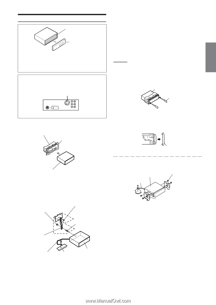
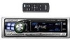
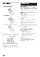
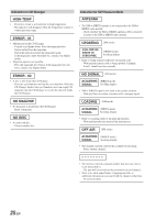
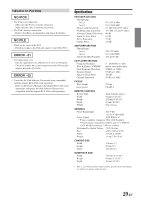
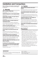
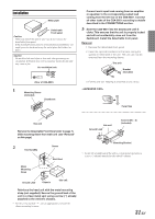
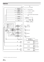
Installation Metal plate Detachable Front panel Caution When you install this unit in your car, do not remove the detachable front panel. If the detachable front panel is removed during installation, you might press too hard and warp the metal plate that holds it in place. Caution Do not block the unit's fan or heat sink, thus preventing air circulation. If blocked, heat will accumulate inside the unit and may cause a fire. Air ventilation hole (Rear of CDA-9851) 1 Mounting Sleeve (Included) Dashboard Connect each input lead coming from an amplifier or equalizer to the corresponding output lead coming from the left rear of the CDA-9851. Connect all other leads of the CDA-9851 according to details described in the CONNECTlONS section. 3 Slide the CDA-9851 into the dashboard until it clicks. This ensures that the unit is properly locked and will not accidentally come out from the dashboard. Install the detachable front panel. Removal 1 Remove the detachable front panel. 2 Insert the optional brackets into the back, along the guides on either side of the unit. The unit can now be removed from the mounting sleeve. This unit Bracket (Included) 3 Pull the unit out, keeping it unlocked as you do so. Face Plate this unit Remove the Detachable Front Panel (refer to page 7). Slide mounting sleeve from main unit (see "Removal" on this page). 2 Hex Nut (M5) Screw *2 Bolt Stud this unit Ground Lead*3 Screws (M5 × 8) (Included) Mounting Bracket • Secure the ground lead of the unit to a clean metal spot using a screw (*3) already attached to the vehicle's chassis. Metal Mounting Strap *1 Ground Lead Chassis this unit Reinforce the head unit with the metal mounting strap (not supplied). Secure the ground lead of the unit to a clean metal spot using a screw (*1) already attached to the vehicle's chassis. • For the screw marked "*2", use an appropriate screw for the chosen mounting location. 31-EN
-
 1
1 -
2
-
3
-
4
-
5
-
6
-
7
-
8
-
9
-
10
-
11
-
12
-
13
-
14
-
15
-
16
-
17
-
18
-
19
-
20
-
21
-
22
-
23
-
24
-
25
-
26
-
 27
27 -
 28
28 -
 29
29 -
 30
30 -
 31
31 -
 32
32 -
 33
33 -
 34
34 -
 35
35 -
 36
36 -
 37
37 -
38
-
39
-
40
-
41
-
42
-
43
-
44
-
45
-
46
-
47
-
48
-
49
-
50
-
51
-
52
-
53
-
54
-
55
-
56
-
57
-
58
-
59
-
60
-
61
-
62
-
63
-
64
-
65
-
66
-
67
-
68
-
69
-
70
-
71
-
72
-
73
-
74
-
75
-
76
-
77
-
78
-
79
-
80
-
81
-
82
-
83
-
84
-
85
-
86
-
87
-
88
-
89
-
90
-
91
-
92
-
93
-
94
-
95
-
96
-
97
-
98
-
99
-
100
-
101
-
102
-
103
 |
 |