Alpine KTX-GM8K2 Installation Instructions - Page 1
Alpine KTX-GM8K2 Manual
 |
View all Alpine KTX-GM8K2 manuals
Add to My Manuals
Save this manual to your list of manuals |
Page 1 highlights
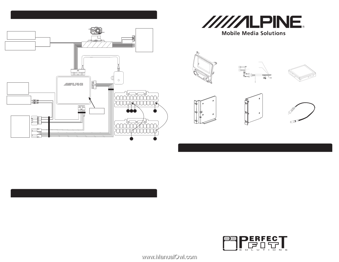
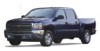
Corporate logo + Domain message clean print proof 15A 15A Wiring Harness Diagram To Foot Brake (+) at switch above pedal To aftermarket amplifier remote turn on Yellow/Black Blue/White To Camera 10A Connector (Steering Wheel Controls) Audio Video Navigation System To Head Unit Power Connector Perfect Fit For Select 2014+ Chevrolet/GMC Trucks (No Bose System) Installation Manual KTX-GM8K2 To Chime Module LOGO: PERFECT FIT To Steering Remote Input (Pigtail) Green/Black Aux In to factory 3.5mm Input INE-Z928HD Camera Harness GM Trim Panel x 1 ●Corporate message Power Harness x 1 Radio Replacement and Steering Wheel Module x 1 Empty Port 20 18 16 2 Perfect Fit Harness To GM Vehicle Harness 18 2 Left Bracket x 1 Right Bracket x 1 GM Antenna Adapter 1. Adding rear-view camera: Introduction A) INE-Z928HD wire colors: Pin 2 - Green White, Pin 16 - Red, Pin 18 - White, Pin 20 - Black B) Perfect Fit wire colors: Pin 2 - Violet/White, Pin 18 - Blue/Yellow This KTX-GM8K2 Perfect Fit installation kit is for Select 2014+ Chevrolet/GMC Trucks (without the C) Remove all pins from above diagram Bose system). Included are all the parts needed to install your Alpine INE-Z928HD or Alpine X008 Harness D) Replace pins 2 & 18 from INE-Z928HD Camera Harness with pins from Perfect Fit Audio Video Navigation system. KTX-GM8K2 Perfect Fit installation kit also includes an interface T h e m e : D a s h I n t e g r a t i othnat will retain factory featureTshseucmh eas: ODnSatsarh, veI nhitcelegsretatitnigos,nsteering wheel controls (SWC), 2. The interface comes pre-programmed for all of the vehicles factory SWC functions and does not require programming. Application: Standard front data and bus dreriavrepnaoruktapsustisstsuacnhdAawpsaprrenl tiiancignaectdhi ioamcnecs:eswSshomernyatphlolewoerrig(RinAaPl r)a, dveiohiicsleresmpoeveedds.eItnaslosro(VpSroSv)i,des 3. The LED will flash whenever a user programmable SWC button is pressed. illumination, reverse trigger and parking brake. Refer to the individual instruction sections of this manual to remove your vehicle's factory radio and assemble the kit. Liability Disclaimer Due to changes in design and manufacturing that may occur with your specific vehicle, it is important that you do not rely solely on vehicle information contained in this installation manual, such as dash disassembly, wire harness, and codes. Such information should be confirmed with the vehicle manufacturer. Alpine Electronics, Inc. and its affiliated companies is not responsible for damage that may occur to you or your automobile during the installation of the Perfect Fit Kit. If you have any further questions, feel free to contact Alpine Tech Support at 1-800-NAV-HELP. ALPINE ELECTRONICS OF AMERICA, INC., 19145 Gramercy Place, Torrance, CA 90501, U.S.A Do not send products to this address. Call the toll free number or visit the website to locate a service center. Caution! Disconnect your vehicle's negative battery terminal before the installation to help prevent electrical damage. We recommend the use of a digital multimeter to check vehicle wiring. Do not use a test light! A test light or grounded wire probe can cause damage to the vehicle's computer and/or diagnostic systems. Avoid all factory airbag wiring. Airbags can accidentally deploy causing serious injury or even death. Notes: • See your vehicle's instructions for any special tools your installation might require. • Read all instructions accompanying your car stereo for proper wiring and mounting instructions. 4 1
-
 1
1 -
 2
2
 |
 |