American Standard 3208.016.222 Installation Instructions - Page 3
Adjustments - toilet parts
 |
UPC - 033056485125
View all American Standard 3208.016.222 manuals
Add to My Manuals
Save this manual to your list of manuals |
Page 3 highlights
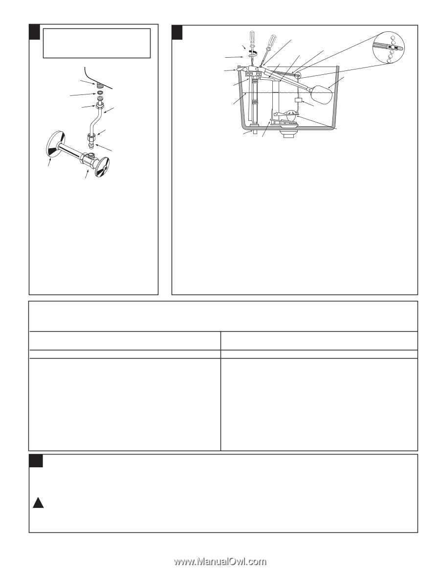
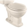
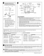
8 CAUTION: Overtightening of COUPLING NUT could result in breakage and potential flooding. WATER INLET WASHER COUPLING NUT TANK FLEXIBLE SUPPLY VALVE NUT COMPRESSION COLLAR TRIM PLATE VALVE CONNECT WATER SUPPLY a. Connect water supply line between shutoff valve and tank water inlet fitting. Tighten COUPLING NUT 1/4 turn beyond hand tight. Check that refill tube is inserted into overflow tube. b. Turn on supply valve and allow tank to fill until float rises to shutoff position. c. Check for leakage at fittings, tighten or correct as needed. d. Do not use plumber's putty to seal these fittings. 9 TO RAISE WATER LEVEL + TO LOWER WATER - LEVEL TRIP LEVER C L WATER CONTROL ASSEMBLY FLOW RATE ADJUSTMENT OVERFLOW TUBE REFILL TUBE LIFT ROD FLOAT BALL WATER LINE LEVEL WATER INLET FLUSH VALVE FLUSH VALVE FLOAT FLAPPER ASSEMBLY FIG. 10A ADJUSTMENTS a. Flush tank and check that tank fills and shuts off within 30 to 60 seconds, and tank water level is set as specified on tank rear wall. b. To adjust water level: turn water level adjustment screw counterclockwise to raise level; turn adjustment screw clockwise to lower level. c. To adjust flow rate (tank fill time): turn flow rate adjustment screw clockwise to decrease flow rate (increase fill time); turn adjustment screw counterclockwise to increase flow rate (decrease fill time). d. Carefully position tank cover on tank. e. The flush valve float has been factory set and does not require adjustments. Repositioning of the float will change the amount of water used which may effect the toilet's performance. f. If bowl fails to siphon, an adjustment may be required with the lift chain. Simply remove the bead chain from the retainment clip (see Fig. 10A) and take up slack on the chain, and reinsert on lift rod. Make sure the chain is not too taught. REPAIR PARTS LIST Repair parts are determined by toilet tank number which can be found marked inside tank. NOTE: "XXX" represents color or trim finish options. Specify when ordering. FOR 4094 ANTIQUITY, 4095 REPERTOIRE, AND 4094.702 WILLIAMSBURG PART NO. DESCRIPTION 730288-XXX0A 730535-XXX0A 034783-XXX0A 738462-0070A 738181-0070A 047158-0070A 738258 -0070A TRIP LEVER TRIP LEVER (WILLIAMSBURG ONLY) BOLT CAP KIT (INCL 2 COVERS & WASHERS) WATER CONTROL ASS'y W FLOAT BALL FLUSH VALVE COUPLING KIT, BOWL-TO-TANK FLAPPER ASSEMBLY FOR 4074.039 HERITAGE PART NO. DESCRIPTION 730283-XXX0A TRIP LEVER 047227-XXX0A BOLT CAP COVER PLATE KIT #207 738352-0070A 738181-0070A 047158-0070A 738258 -0070A WATER CONTROL ASS'y W FLOAT BALL FLUSH VALVE COUPLING KIT, BOWL-TO-TANK FLAPPER ASSEMBLY 11 CARE AND CLEANING When cleaning your toilet, wash it with mild, soapy water, rinse thoroughly with clear water and dry with a soft cloth. Avoid detergents, disinfectants, or cleaning products in aerosol cans. NEVER use abrasive scouring powders or abrasive pads on your toilet seat. Some bathroom chemicals and cosmetics may damage the seat's finish. ! WARNING: Do not use in-tank cleaners. Products containing chlorine (calcium hypochlorite) can seriously damage fittings in the tank. This damage can cause leakage and property damage. American Standard shall not be responsible or liable for any tank fitting damage caused by the use of cleaners containing chlorine (calcium hypochlorite). - 3 - 730489-100 Rev. B
-
 1
1 -
 2
2 -
 3
3 -
 4
4
 |
 |