Ariens Classic LM 21 Owners Manual - Page 22
WHEEL DRIVE CONTROL, ADJUSTMENT, Self-Propelled Models, bracket. See
 |
View all Ariens Classic LM 21 manuals
Add to My Manuals
Save this manual to your list of manuals |
Page 22 highlights
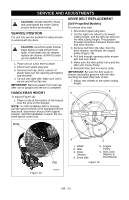
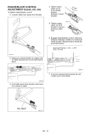
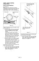
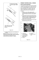
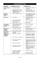
WHEEL DRIVE CONTROL ADJUSTMENT (Self-Propelled Models) See Figure 16. NOTE: When the wheel drive control is disengaged, the gap between the friction disc and the aluminum drive plate should be approximately .030" (.7mm). See Figure 16. Friction Disc Aluminum Drive Plate Approx. .030" (0.7mm) To increase the gap, loosen the lower cable nut. Figure 16 Check the adjustment with the engine off and with the engine on: 1. With the engine off and the wheel drive control disengaged, push the mower forward in both fast and slow speed settings. If the mower pushes freely, the gap between the friction disc and aluminum drive plate is sufficient. If the mower is difficult to push or the rear wheels drag, increase the gap between the friction disc and aluminum drive plate. 2. With the engine on, the mower should start moving as soon as the wheel drive control begins to pull on the cable. If the wheel drive control requires a long travel before the mower begins to pull, decrease the gap between the friction disc and aluminum drive plate. To increase the gap between the friction disc and the aluminum drive plate: 1. Loosen the lower cable nut on the wheel drive control cable, and then tighten the upper cable nut against the adjuster bracket. See Figure 17. Then tighten the upper cable nut against the bracket. Figure 17 To decrease the gap between the friction disc and the aluminum drive plate: 1. Loosen the upper cable nut on the wheel drive control cable, and then tighten the lower cable nut against the adjuster bracket. See Figure 18. GB - 22
-
 1
1 -
2
-
3
-
4
-
5
-
6
-
7
-
8
-
9
-
10
-
11
-
12
-
13
-
14
-
15
-
16
-
 17
17 -
 18
18 -
 19
19 -
 20
20 -
 21
21 -
 22
22 -
 23
23 -
 24
24 -
 25
25 -
 26
26 -
 27
27 -
28
-
29
-
30
-
31
-
32
 |
 |
