Ariens Hydro Pro 36 Owners Manual - Page 10
Check Function of all Controls
 |
View all Ariens Hydro Pro 36 manuals
Add to My Manuals
Save this manual to your list of manuals |
Page 10 highlights
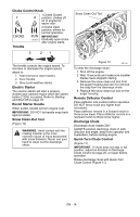
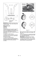
Remote Deflector Control (Figure 7) Connect the cable end to the cable anchor on the discharge deflector before clipping the cable to the cable bracket on the discharge chute. 1. Route deflector remote cable along the left side of the chute pedestal. 2. Insert the barrel on the cable end into the bracket on left side of chute deflector (Figure 7). 3. Hold seal out of the way while routing the cable through the bracket on the left side of the discharge chute, and then push the cable fitting into the bracket. 4. Push the seal securely over the end of the cable fitting to prevent water from entering the cable. Check deflector travel. Adjust nut on cable end under handlebar to obtain full travel, if necessary (see Remote Deflector Control on page 24). 2 3 1 3 5 4 1. Cable Anchor 2. Cable End 3. Deflector Cable 4. Cable Fitting 5. Cable Bracket Figure 7 OS7070 Check Function of Dual Handle Interlock Without the engine running, press down (engage) both clutch levers. Release attachment clutch lever. Attachment clutch should remain engaged until traction clutch lever is released, then both clutches must disengage. If they do not, contact your Dealer for repairs. Check Tire Pressure (926053, 054, 055) Check tire pressure and adjust to the pressure listed on tire sidewall. CAUTION: Avoid injury! Explosive separation of tire and rim parts is possible when they are serviced incorrectly: • Do not attempt to mount a tire without the proper equipment and experience to perform the job. • Do not inflate the tires above the recommended pressure. • Do not weld or heat a wheel and tire assembly. Heat can cause an increase in air pressure resulting in an explosion. Welding can structurally weaken or deform the wheel. • Do not stand in front or over the tire assembly when inflating. Use a clip-on chuck and extension hose long enough to allow you to stand to one side. Check Track Tension (926056) Check tracking of unit with the differential locked, and tension of tracks (see Track Tension Adjustment on page 29). Check Auger Gearcase Oil Check oil level in auger gearcase (see Check Auger Gearcase on page 21). Check Engine Crankcase Oil IMPORTANT: The engine may be shipped with oil in crankcase. Refer to Engine Manual for detailed instructions. Fill Fuel Tank Fill fuel tank. DO NOT OVERFILL! See FILLING FUEL TANK on page 17. Setting Neutral Position Set neutral position of speed selector. See Speed Selector Adjustment on page 25. Check Function of all Controls Ensure unit runs and performs properly. Refer to OPERATION on page 13. Run-in Attachment Belt 1. Start unit in a well-ventilated area according to Starting and Shut Off on page 18. 2. Engage attachment clutch lever and run attachment for about 15 minutes. 3. Stop unit, wait for all moving parts to stop, and remove spark plug wire. 4. Adjust belt finger, if necessary. See Check Belt Finger Clearance on page 27. 5. Adjust clutch idler according to Attachment Clutch/Brake Adjustment on page 25. EN - 10
-
 1
1 -
2
-
3
-
4
-
 5
5 -
 6
6 -
 7
7 -
 8
8 -
 9
9 -
 10
10 -
 11
11 -
 12
12 -
 13
13 -
 14
14 -
 15
15 -
16
-
17
-
18
-
19
-
20
-
21
-
22
-
23
-
24
-
25
-
26
-
27
-
28
-
29
-
30
-
31
-
32
-
33
-
34
-
35
-
36
-
37
-
38
 |
 |
