Ariens Max Zoom 60 Owners Manual - Page 12
Assembly, UNIT ASSEMBLY - in
 |
View all Ariens Max Zoom 60 manuals
Add to My Manuals
Save this manual to your list of manuals |
Page 12 highlights
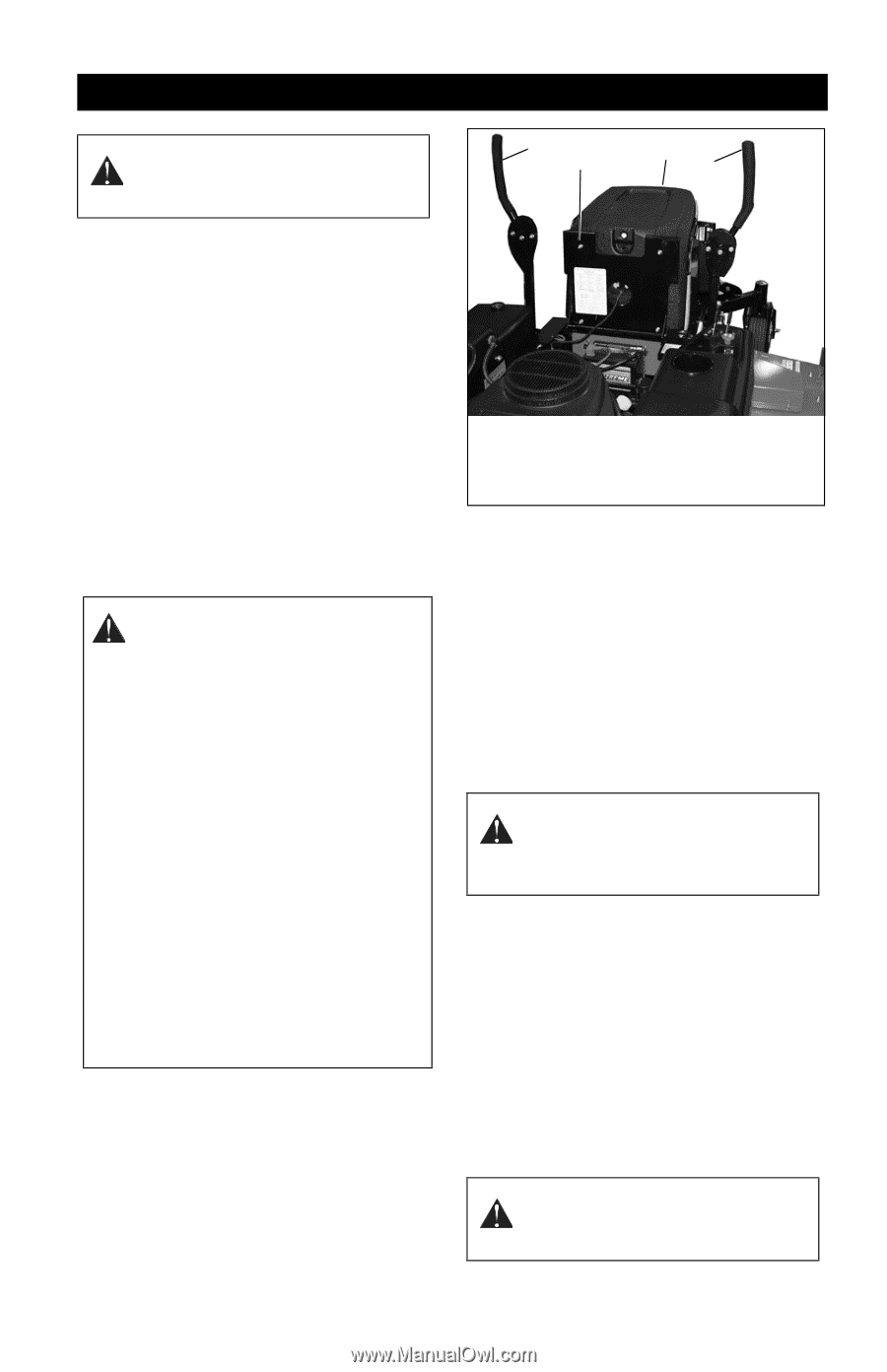
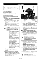
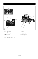
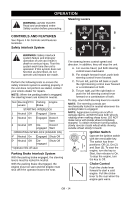
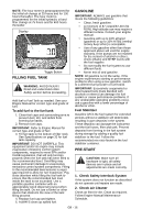
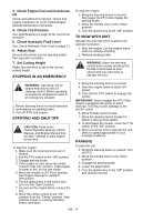
ASSEMBLY WARNING: AVOID INJURY. Read and understand entire Safety section before proceeding. 1 3 21 UNIT ASSEMBLY Package Contents: Unit, Mower Deck and Literature Pack Preparation Checklist Refer to the Owner/Operator manual as required. 1. Unpack Unit - Remove shrink wrap and packaging materials. 2. Remove Unit From Container - Open Bypass Valves (dump valves) (See Moving the Unit with the Engine Off on page 18). Push unit from container onto a level surface. Close the bypass valves. 3. Tires - See Specifications on page 33. CAUTION: Avoid injury! Explosive separation of tire and rim parts is possible when they are serviced incorrectly: • Do not attempt to mount a tire without the proper equipment and experience to perform the job. • Do not inflate the tires above the recommended pressure. • Do not weld or heat a wheel and tire assembly. Heat can cause an increase in air pressure resulting in an explosion. Welding can structurally weaken or deform the wheel. • Do not stand in front or over the tire assembly when inflating. Use a clip-on chuck and extension hose long enough to allow you to stand to one side. 4. Seat - See Seat Adjustments on page 15 and Service Position on page 20. 5. Position Steering Levers - Remove eccentric spacers and rotate steering levers to the operating position. Reinstall spacers. Tighten hardware securely. See Aligning the Steering Levers (Figure 14) on page 25. 1. Steering Levers 2. Seat 3. Mounting Hardware Figure 3 OF4110 6. Battery - Remove battery from unit and charge (See Battery on page 23). 7. Check Engine Crankcase - Check and add oil if needed. See Engine Manual for specifications. 8. Fill Engine Fuel Tank - Fill fuel tank. DO NOT OVERFILL! See Filling Fuel Tank on page 16. NOTE: See engine manual for fuel type. 9. Hardware - Check for loose hardware. 10. Check Safety Interlock System - Check to see that the interlock system operates correctly (See Safety Interlock System on page 14). WARNING: FAILURE OF INTERLOCK together with improper operation can result in severe personal injury. 11. Lubrication - Lubricate all fittings per maintenance label under seat and check hydrostat oil level (See Lubricate Unit on page 24). 12. On 60-inch Decks: Remove the discharge chute from the transport position and place the discharge chute in the operating position. 13. Level Deck - Check unit to ensure deck level set at factory has been maintained (See Leveling the Mower Deck on page 30). 14. Check Function of all Controls - Ensure unit runs and performs properly. WARNING: FAILURE OF CONTROLS could result in death or serious injury. GB - 12
-
 1
1 -
2
-
3
-
4
-
5
-
6
-
 7
7 -
 8
8 -
 9
9 -
 10
10 -
 11
11 -
 12
12 -
 13
13 -
 14
14 -
 15
15 -
 16
16 -
 17
17 -
18
-
19
-
20
-
21
-
22
-
23
-
24
-
25
-
26
-
27
-
28
-
29
-
30
-
31
-
32
-
33
-
34
-
35
-
36
-
37
-
38
 |
 |