Asko T701 User manual Use & Care Guide Asko T701,721,761,781 - Page 4
Installation Instructions - not venting
 |
View all Asko T701 manuals
Add to My Manuals
Save this manual to your list of manuals |
Page 4 highlights
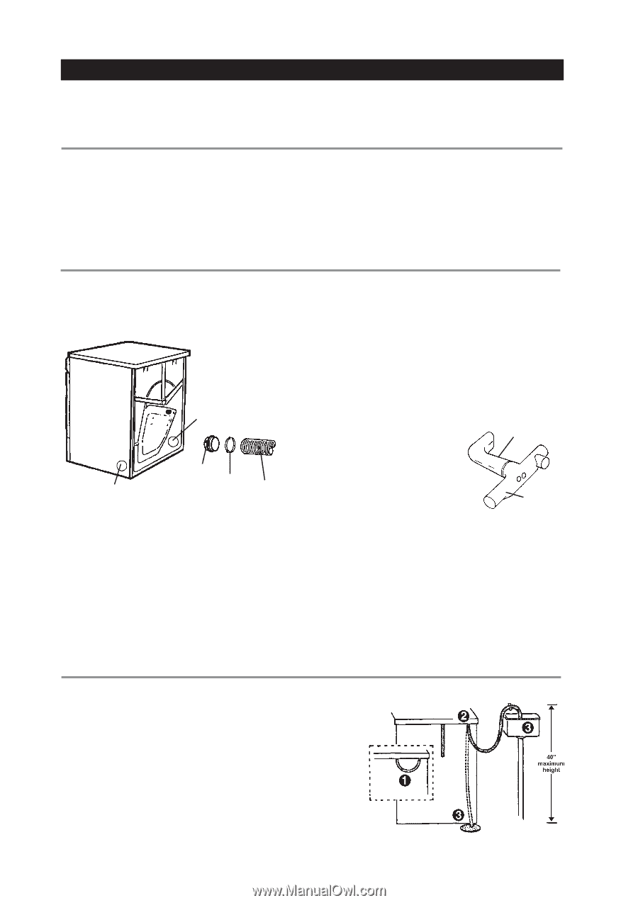
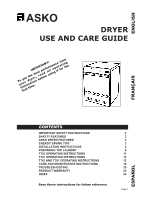
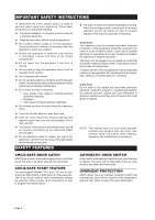
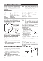
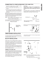
INSTALLATION INSTRUCTIONS Read these instructions carefully and completely before you install the machine. The installation should be carried out by a qualified person who is familiar with all local codes and ordinances for electrical and plumbing connections. SPECIFICATIONS Height Width Depth Weight Drum material 33-1/2"-34-1/2 (850-876 mm) 23-7/16" (595 mm) Plus exhaust hose connection T761/T781: 23-7/16" (595 mm) T701/T721: 24-7/16" (620 mm) 86 lbs (39 kg) Stainless Steel NOTE: Cosmetic damage must be reported to your dealer within five days from the date of purchase. After unpacking the dryer, thoroughly check the unit for cosmetic damage. Outer casing Power requirement For connection Internal fuse Heating element Stove-enamelled hot-dipped galvanized steel 2800 watts Single-phase, 230 V, 30 Amp 15 amp. 2500 watts CONNECTING AIR EXHAUST (T701 AND T761) The exhaust hose can be connected at the rear or on either side of the dryer. When the machine is delivered, the exhaust outlet at the rear is open. The exhaust hose can be connected at the rear or on either side of the dryer. Rear Exhaust Outlet Side Exhaust Outlet Stub Clamp Hose (not supplied) The dryer is shipped with a stub pipe already installed on the rear exhaust outlet. The consumer or installer must purchase a UL-CSA-approved exhaust hose. Rear Outlet Hose Connection To connect the exhaust hose to the rear outlet, follow the steps below: NOTE: After you push the dryer into place, check for kinks in the hose. (Be careful not to use too much hose, because it could reduce drying efficiency.) CONNECTING THE VENT HOSE TO THE LEFT OR RIGHT SIDE OUTLET To connect the exhaust hose to the left or right side outlet, follow the steps below: 1. Using a flathead screw- driver, turn the exhaust Vent outlet cover to align the tabs holding the cover in place. Remove the cover. 2. Remove the stub pipe from the rear exhaust outlet. 3. Place the stub pipe in the outlet you plan to use. T-Tube 4. Follow the instructions for the rear outlet hose connection. 5. Use the exhaust outlet cover you removed from the side to cover the rear exhaust outlet. 1. Push the hose onto the stub pipe and secure it with a clamp. 2. With the hose attached, insert the stub pipe into the hole. It should snap into place. WARNING! To reduce the risk of fire, this appliance must be exhausted OUTDOORS or the equivalent. Never cover the end of the dryer stub or vent hose with anything to catch lint, except for UL approved vent basket. CONDENSATION DRAIN CONNECTION (T721 AND T781) If possible, you should install the dryer so the condensed water will continuously flow into a drain or sink. To do this, follow the instructions below: 1. Disconnect the short hose (1) from the blue connection. (It's okay to let the hose hang down.) 2. Connect the rubber hose supplied with the dryer to the blue nipple (2). 3. Run the hose to a drain or sink, as illustrated. NOTE: The drain hose must not be more than 40" above the floor. Page 4 Back of dryer
-
 1
1 -
 2
2 -
 3
3 -
 4
4 -
 5
5 -
 6
6 -
 7
7 -
 8
8 -
 9
9 -
 10
10 -
11
-
12
-
13
-
14
-
15
-
16
-
17
-
18
-
19
-
20
-
21
-
22
-
23
-
24
-
25
-
26
-
27
-
28
-
29
-
30
-
31
-
32
-
33
-
34
-
35
-
36
-
37
-
38
-
39
-
40
-
41
-
42
-
43
-
44
-
45
-
46
-
47
-
48
-
49
-
50
-
51
-
52
-
53
-
54
-
55
-
56
-
57
-
58
-
59
-
60
-
61
-
62
-
63
-
64
-
65
-
66
-
67
-
68
-
69
-
70
-
71
-
72
 |
 |