Asus A7N8X-VM 400 A7N8X-VM/400 User's Manual - Page 28
Product Information, Internal audio connectors 4 pin CD1, AUX1, Digital Audio Connector 6
 |
View all Asus A7N8X-VM 400 manuals
Add to My Manuals
Save this manual to your list of manuals |
Page 28 highlights
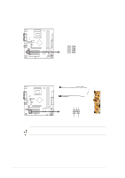
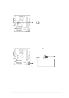
10. Internal audio connectors (4 pin CD1, AUX1) These connectors allow you to receive stereo audio input from sound sources such as a CD-ROM, TV tuner, MPEG card or modem. A7N8X-VM 400 AUX1 (White) CD1 (Black) Left Audio Channel Ground Right Audio Channel A7N8X-VM 400 Internal Audio Connectors 11. Digital Audio Connector (6-1 pin SPDIF1) This connector is for optional S/PDIF audio module that allows digital instead of analog sound input and output. SPDIF_OUT +5V SPDIF_IN GND GND A7N8X-VM 400 SPDIF1 1 A7N8X-VM 400 Digital Audio Connector When you input sound for S/PDIF IN, the LINE_OUT will output the sound. Mute LINE_OUT to impede sound output from S/PDIF IN. 1-18 Chapter 1: Product Information
-
 1
1 -
2
-
3
-
4
-
5
-
6
-
7
-
8
-
9
-
10
-
11
-
12
-
13
-
14
-
15
-
16
-
17
-
18
-
19
-
20
-
21
-
22
-
 23
23 -
 24
24 -
 25
25 -
 26
26 -
 27
27 -
 28
28 -
 29
29 -
 30
30 -
 31
31 -
 32
32 -
 33
33 -
34
-
35
-
36
-
37
-
38
-
39
-
40
-
41
-
42
-
43
-
44
-
45
-
46
-
47
-
48
-
49
-
50
-
51
-
52
-
53
-
54
-
55
-
56
-
57
-
58
-
59
-
60
 |
 |

1-18
Chapter 1:
Product Information
10. Internal audio connectors (4 pin CD1, AUX1)
These connectors allow you to receive stereo audio input from sound sources
such as a CD-ROM, TV tuner, MPEG card or modem.
11.
Digital Audio Connector (6-1 pin SPDIF1)
This connector is for optional S/PDIF audio module that allows digital instead
of analog sound input and output.
When you input sound for S/PDIF IN, the LINE_OUT will output the
sound. Mute LINE_OUT to impede sound output from S/PDIF IN.
A7N8X-VM 400
A7N8X-VM 400 Internal Audio Connectors
AUX1 (White)
CD1 (Black)
Right Audio Channel
Left Audio Channel
Ground
A7N8X-VM 400
A7N8X-VM 400 Digital Audio Connector
SPDIF1
GND
+5V
SPDIF_IN
SPDIF_OUT
1
GND