Asus A7S333 A7S333 User Manual - Page 51
ATX Power Switch / Soft-Off Switch Lead 2 pin PWR - motherboard drivers
 |
View all Asus A7S333 manuals
Add to My Manuals
Save this manual to your list of manuals |
Page 51 highlights
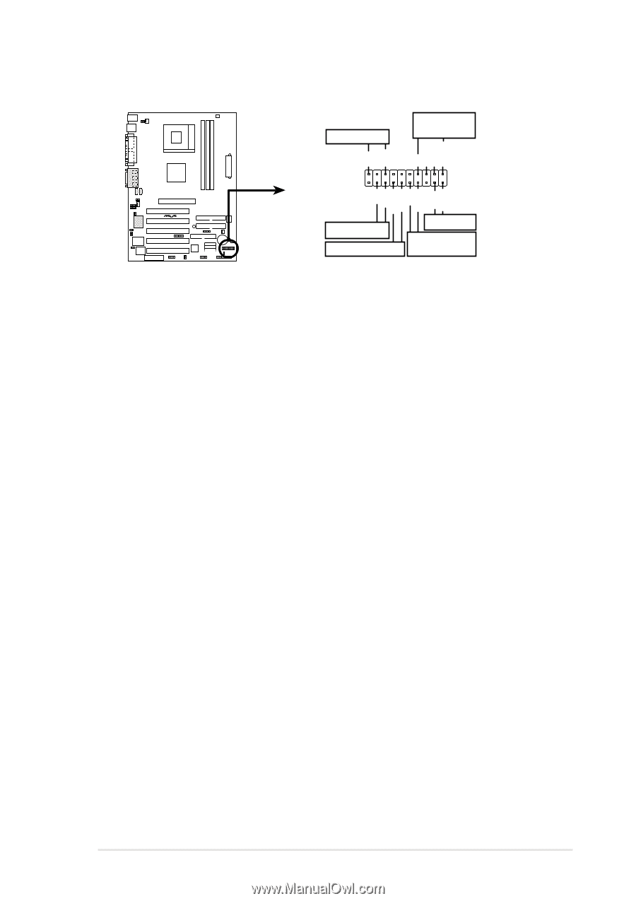
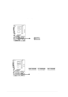
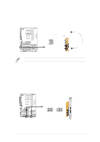
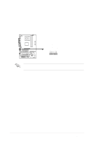
The following 20-pin PANEL illustration is for items 22-27: Power LED Speaker Connector +5 V PLED +5V Ground Ground Speaker +5 V MLED ExtSMI# Ground PWR Ground Reset Ground ® A7S333 Message LED SMI Lead Reset SW ATX Power Switch* * Requires an ATX power supply. A7S333 System Panel Connectors 22) System Power LED Lead (3-1 pin PLED) This 3-1 pin connector supplies the system power LED. The LED lights up when the system power is on, and the LED blinks when the system is in sleep or soft-off mode. 23) System Warning Speaker Lead (4 pin SPEAKER) This 4-pin connector supplies the case-mounted speaker to sound system beeps and warnings. 24) System Message LED Lead (2 pin MLED) This 2-pin connector supports the system message LED to indicate receipt of messages from a fax/modem. The normal status for this LED is ON, when there is no incoming data signal. The LED blinks when data is received. The system message LED feature requires an ACPI OS and driver support. 25) System Management Interrupt Lead (2 pin SMI) This 2-pin connector permits switching to suspend mode, or "Green" mode, in which system activity is instantly decreased to save power and to expand the life of certain system components. Attach the case-mounted suspend switch this 2-pin connector. 26) ATX Power Switch / Soft-Off Switch Lead (2 pin PWR) The system power is controlled by a momentary switch attached to this connector. Pressing the button switches the system between ON and SLEEP, or ON and SOFT OFF, depending on the BIOS or OS settings. Pressing the button while in the ON mode for more than 4 seconds turns the system off. 27) Reset Switch Lead (2-pin RESET) This 2-pin connector supports the case-mounted reset switch for rebooting the system without turning off the power switch. ASUS A7S333 motherboard user guide 39
-
 1
1 -
2
-
3
-
4
-
5
-
6
-
7
-
8
-
9
-
10
-
11
-
12
-
13
-
14
-
15
-
16
-
17
-
18
-
19
-
20
-
21
-
22
-
23
-
24
-
25
-
26
-
27
-
28
-
29
-
30
-
31
-
32
-
33
-
34
-
35
-
36
-
37
-
38
-
39
-
40
-
41
-
42
-
43
-
44
-
45
-
 46
46 -
 47
47 -
 48
48 -
 49
49 -
 50
50 -
 51
51 -
 52
52 -
 53
53 -
 54
54 -
 55
55 -
 56
56 -
57
-
58
-
59
-
60
-
61
-
62
-
63
-
64
-
65
-
66
-
67
-
68
-
69
-
70
-
71
-
72
-
73
-
74
-
75
-
76
-
77
-
78
-
79
-
80
-
81
-
82
-
83
-
84
-
85
-
86
-
87
-
88
-
89
-
90
-
91
-
92
-
93
-
94
-
95
-
96
-
97
-
98
-
99
-
100
-
101
-
102
-
103
-
104
-
105
-
106
-
107
-
108
-
109
-
110
-
111
-
112
-
113
-
114
-
115
-
116
-
117
-
118
-
119
-
120
-
121
-
122
-
123
-
124
-
125
-
126
 |
 |