Asus A7U User Manual - Page 19
Right Side, Optical Drive Emergency Eject, Optical Drive, Power DC Input - specifications
 |
View all Asus A7U manuals
Add to My Manuals
Save this manual to your list of manuals |
Page 19 highlights
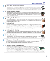
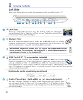
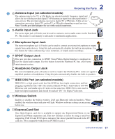
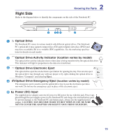
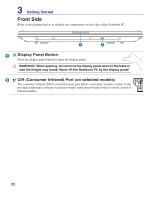
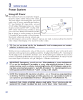
2 Knowing the Parts Right Side Refer to the diagram below to identify the components on this side of the Notebook PC. 1 23 4 5 1 Optical Drive The Notebook PC comes in various models with different optical drives. The Notebook PC's optical drive may support compact discs (CD) and/or digital video discs (DVD) and may have recordable (R) or re-writable (RW) capabilities. See the marketing specifica- tions for details on each model. 2 Optical Drive Activity Indicator (location varies by model) The optical drive activity indicator shows when data is being transferred by the optical disk drive. This indicator will light in proportion to the data size transferred. 3 Optical Drive Electronic Eject The optical drive eject has an electronic eject button for opening the tray. You can also eject the optical drive tray through any software player or by right clicking the optical drive in Windows "Computer" and selecting Eject. 4 Optical Drive Emergency Eject (location varies by model) The emergency eject is used to eject the optical drive tray in case the electronic eject does not work. Do not use the emergency eject in place of the electronic eject. 5 Power (DC) Input The supplied power adapter converts AC power to DC power for use with this jack. Power sup- plied through this jack supplies power to the Notebook PC and charges the internal battery pack. To prevent damage to the Notebook PC and battery pack, always use the supplied power adapter. CAUTION: MAY BECOME WARM TO HOT WHEN IN USE. BE SURE NOT TO COVER THE ADAPTER AND KEEP IT AWAY FROM YOUR BODY. 19
-
 1
1 -
2
-
3
-
4
-
5
-
6
-
7
-
8
-
9
-
10
-
11
-
12
-
13
-
 14
14 -
 15
15 -
 16
16 -
 17
17 -
 18
18 -
 19
19 -
 20
20 -
 21
21 -
 22
22 -
 23
23 -
 24
24 -
25
-
26
-
27
-
28
-
29
-
30
-
31
-
32
-
33
-
34
-
35
-
36
-
37
-
38
-
39
-
40
-
41
-
42
-
43
-
44
-
45
-
46
-
47
-
48
-
49
-
50
-
51
-
52
-
53
-
54
-
55
-
56
-
57
-
58
-
59
-
60
-
61
-
62
-
63
-
64
-
65
-
66
-
67
-
68
-
69
-
70
-
71
-
72
-
73
-
74
-
75
-
76
-
77
-
78
-
79
-
80
-
81
-
82
-
83
-
84
-
85
-
86
-
87
-
88
-
89
 |
 |
