Asus A7V600 A7V600 User Manual
Asus A7V600 Manual
 |
View all Asus A7V600 manuals
Add to My Manuals
Save this manual to your list of manuals |
Asus A7V600 manual content summary:
- Asus A7V600 | A7V600 User Manual - Page 1
Motherboard A7V600 User Guide - Asus A7V600 | A7V600 User Manual - Page 2
express written permission of ASUSTeK COMPUTER INC. ("ASUS"). Product warranty or service will not be extended if: (1) the ASUS HAS BEEN ADVISED OF THE POSSIBILITY OF SUCH DAMAGES ARISING FROM ANY DEFECT OR ERROR IN THIS MANUAL OR PRODUCT. SPECIFICATIONS AND INFORMATION CONTAINED IN THIS MANUAL - Asus A7V600 | A7V600 User Manual - Page 3
guide vii ASUS contact information viii A7V600 specifications summary ix Chapter 1: Product introduction 1.1 Welcome 1-2 1.2 Package contents 1-2 1.3 Special Features 1-3 1.3.1 Product highlights 1-3 1.3.2 Value-added solutions 1-5 1.4 Motherboard components 1-6 1.4.1 Core specifications - Asus A7V600 | A7V600 User Manual - Page 4
3.2.1 Running the support CD 3-2 3.2.2 Drivers menu 3-3 3.2.3 Utilities menu 3-3 3.2.4 ASUS Contact Information 3-4 3.3 ASUS Instant Music Lite 3-5 3.4 RAID 0 / RAID 1 / RAID 0 + 1 Configurations 3-7 3.4.1 Install the Serial ATA (SATA) hard disks 3-8 3.4.2 Enter VIA® Tech RAID BIOS Utility - Asus A7V600 | A7V600 User Manual - Page 5
. This equipment generates, uses and can radiate radio frequency energy and, if not installed and used in accordance with manufacturer's instructions, may cause harmful interference to radio communications. However, there is no guarantee that interference will not occur in a particular installation - Asus A7V600 | A7V600 User Manual - Page 6
Contact a qualified service technician or your retailer. Operation safety • Before installing the motherboard and adding devices on it, carefully read all the manuals that came with . • If you encounter technical problems with the product, contact a qualified service technician or your retailer. vi - Asus A7V600 | A7V600 User Manual - Page 7
this guide To make sure that you perform certain tasks properly, take note of the following symbols used throughout this manual. WARNING updates. 1. ASUS Websites The ASUS websites worldwide provide updated information on ASUS hardware and software products. The ASUS websites are listed in the ASUS - Asus A7V600 | A7V600 User Manual - Page 8
44370 Nobel Drive, Fremont, CA 94538, USA General Fax: +1-502-933-8713 General Email: [email protected] Technical Support Support Fax: +1-502-933-8713 General Support: +1-502-995-0883 Notebook Support: +1-510-739-3777 x5110 Web Site: usa.asus.com Support Email: [email protected] ASUS COMPUTER - Asus A7V600 | A7V600 User Manual - Page 9
A7V600 specifications summary CPU Chipset Front Side Bus (FSB) Memory Expansion slots Storage Audio LAN Special Features Overclocking Features Rear Panel I/O Socket A for AMD Athlon XP/Athlon/Duron with Thoroughbred/Barton Core support Northbridge: VIA KT600 Southbridge: VIA VT8237 400/333/266/ - Asus A7V600 | A7V600 User Manual - Page 10
A7V600 specifications summary (Cont') Internal I/O Connectors BIOS features Industry standard Manageability Form Factor Support CD contents CPU/Power/Chassis FAN connectors 20 pin ATX power connector Chassis Intrusion GAME/MIDI connector CD/AUX/Modem audio in S/PDIF out connector Front panel audio - Asus A7V600 | A7V600 User Manual - Page 11
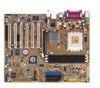
Chapter 1 This chapter gives information about the ASUS A7V600 motherboard that came with the system.This chapter includes the motherboard layout, jumper settings, and connector locations. Motherboard Info ASUS A7V600 Motherboard 1-1 - Asus A7V600 | A7V600 User Manual - Page 12
A7V600 motherboard is loaded with the most advanced technologies to deliver the maximum performance for socket A processors. Based on the advanced VIA KT600 chipset with FSB 400 and DDR 400 support, the ASUS A7V600 also features AGP 8X, Serial ATA, USB 2.0 as well as 6-channel audio, Gigabit LAN - Asus A7V600 | A7V600 User Manual - Page 13
Platform Combining support for the next generation AMD Athlon™ XP processors with 400Mhz Front Side Bus (FSB) with its advanced FastStream64™ Memory Controller Technology and the industry-first integrated Serial ATA/RAID controller on the VIA VT8237 South Bridge, the VIA KT600 provides the highest - Asus A7V600 | A7V600 User Manual - Page 14
Flash BIOS With the ASUS EZ Flash, you can easily update the system BIOS even before loading the operating system. No need to use a DOS-based utility or boot from a floppy disk. ASUS Instant Music Lite This unique feature allows you to playback audio files even without booting the system to Windows - Asus A7V600 | A7V600 User Manual - Page 15
current for critical components. Chassis intrusion detection The motherboard supports chassis intrusion monitoring. A chassis intrusion event is retained in CMOS for more protection. ASUS update This utility allows you to update the motherboard BIOS through a user-friendly interface. Connect to the - Asus A7V600 | A7V600 User Manual - Page 16
components Before you install the motherboard, learn about its major components and available features to facilitate the installation and future upgrades. Refer to the succeeding pages 8 9 17 10 11 16 15 14 19 20 13 12 21 22 23 24 29 28 27 26 25 1-6 Chapter 1: Motherboard Information - Asus A7V600 | A7V600 User Manual - Page 17
specifications 1 CPU socket. Socket 462 (Socket A) surface mount, Zero Insertion Force (ZIF) socket for the AMD Athlon XP/Athlon/Duron Processors. (Note: When using CPUs with FSB 100, the maximum DDR data transfer rate allowed is only at 266Mhz.) 2 North bridge controller. The VIA® KT600 supports - Asus A7V600 | A7V600 User Manual - Page 18
1980 is an AC'97 compliant audio CODEC for PC multimedia systems. 18 Gigabit LAN controller. The 3Com® Gigabit LAN delivers transfer rates up to ten times faster than conventional 10/100 Ethernet connections. Ideal for handling large amounts of data such as video, audio and voice. 19 PS/2 mouse - Asus A7V600 | A7V600 User Manual - Page 19
PRI_IDE SEC_IDE FLOPPY 30.5cm (12.0in) 1.5 Motherboard layout PS/2KBMS T: Mouse B: Keyboard KBPWR Center:Line Out Below:Mic In AUX CD VIA KT600 Chipset PWR_FAN Accelerated Graphics Port (AGP) 3Com 3C940 Gbit LAN FP_AUDIO PCI1 A7V600 PCI2 VIA VT8237 South Bridge SATA2 SATA1 AD1980 CODEC - Asus A7V600 | A7V600 User Manual - Page 20
from the power supply. Failure to do so may cause severe damage to the motherboard, peripherals, and/or components. When lit, the green LED (SB_PWR) indicates that removing or plugging in any motherboard component. A7V600 SB_PWR ® A7V600 Onboard LED ON Standby Power OFF Powered Off Install only 1.5V - Asus A7V600 | A7V600 User Manual - Page 21
as indicated in the image below. 1.7.2 Screw holes Place nine (9) screws into the holes indicated by circles to secure the motherboard to the chassis. Do not overtighten the screws! Doing so may damage the motherboard. Place this side towards the rear of the chassis ASUS A7V600 Motherboard 1-11 - Asus A7V600 | A7V600 User Manual - Page 22
Unit (CPU) The motherboard provides a Socket A (462) for CPU installation. AMD processors offer gigahertz speeds to support all the latest computing platforms and applications. The A7V600 supports AthlonTM XP, AthlonTM, Barton™ and DuronTM processors. A7V600 ® A7V600 Socket A AMD™ CPU CPU NOTCH - Asus A7V600 | A7V600 User Manual - Page 23
-5 DDR400 Two DIMM support only Vendor GEIL Micron Nanya ADATA Size 512MB 512MB 256MB 256 Type DS DS SS SS P/N MAG16UL3264D1TG5A-KC MT16VDDT6464AG-40BC4 NT256D64S88B1G-5T MDOSS6F3G31JB1EAE Chip GL3LC32G88TG-5A MT46V32M8TG-5BC NT5DS32M8BT-5T K4H560838D-TCC4 ASUS A7V600 Motherboard 1-13 - Asus A7V600 | A7V600 User Manual - Page 24
1.10 Expansion slots The A7V600 motherboard has six (6) expansion PCI slots and one (1) AGP 8X slot. The following sub-sections describe the slots and the expansion cards that they support. 1.10.1 Configuring an expansion card After physically installing the expansion card, configure the card by - Asus A7V600 | A7V600 User Manual - Page 25
that supports +1.5V AGP cards only. When you buy an AGP card, make sure that you ask for one with +1.5V specification. Note the notches on the card golden fingers to ensure that they fit the AGP slot on your motherboard. A7V600 Keyed for 1.5v ® A7V600 Accelerated Graphics Port (AGP) ASUS A7V600 - Asus A7V600 | A7V600 User Manual - Page 26
will support the ASUS Wi-Fi module when available. Visit the ASUS website (www.asus.com) for product updates. sequence spread spectrum. The IEEE 802.11b specification allocates the 2.4 GHz frequency band into 14 1, 6, and 11. A7V600 ® WIFI A7V600 WIRELESS Connectors The PCI 6 slot and WiFi slot - Asus A7V600 | A7V600 User Manual - Page 27
value is [Disabled]). This feature requires an ATX power supply that can supply at least 1A on the +5VSB lead, and a corresponding setting in the BIOS (see section 4.5.1 Power Up Control). KBPWR 12 23 A7V600 +5V (Default) +5VSB ® A7V600 Keyboard Power Setting ASUS A7V600 Motherboard 1-17 - Asus A7V600 | A7V600 User Manual - Page 28
battery. 5. Plug the power cord and turn ON the computer. 6. Hold down the key during the boot process and enter BIOS setup to re-enter data. A7V600 ® A7V600 Clear RTC RAM CLRTC 2 1 Clear CMOS 3 2 Normal (Default) 4. VCORE over-voltage (3-pin OVER_VOLT1) When enabled, this jumper allows - Asus A7V600 | A7V600 User Manual - Page 29
IDE connector. If you install two hard disks, you must configure the second drive as a slave device by setting its jumper accordingly. Refer to the hard disk documentation for the jumper settings. BIOS supports specific device bootup. If you have more than two UltraDMA/133/100/66 devices, purchase - Asus A7V600 | A7V600 User Manual - Page 30
(34-1 pin FLOPPY) This connector supports the provided floppy drive ribbon cable. After connecting one end to the motherboard, connect the other end to the floppy drive. (Pin 5 is removed to prevent incorrect insertion when using ribbon cables with pin 5 plug). FLOPPY A7V600 ® NOTE: Orient the red - Asus A7V600 | A7V600 User Manual - Page 31
unstable and may experience difficulty powering up if the power supply is inadequate. ATXPWR1 A7V600 ® A7V600 ATX Power Connector +3.3VDC -12.0VDC GND PS_ON# GND GND GND -5.0VDC +5.0VDC +5.0VDC +3.3VDC +3.3VDC GND +5.0VDC GND +5.0VDC GND PWR_OK +5VSB +12.0VDC ASUS A7V600 Motherboard 1-21 - Asus A7V600 | A7V600 User Manual - Page 32
header is available for additional USB ports. The USB header complies with USB 2.0 specification that supports up to 480 Mbps connection speed. This speed advantage over the conventional 12 Mbps on USB 1.1. If your package came with a USB 2.0 module, connect the USB cable to this header. The module - Asus A7V600 | A7V600 User Manual - Page 33
bracket. Connect the bracket cable to this connector then install the bracket with green port into a slot opening at the back of the system chassis. A7V600 COM2 PIN 1 ® A7V600 Serial COM2 Bracket The COM2 cable is purchased separately. ASUS A7V600 Motherboard 1-23 - Asus A7V600 | A7V600 User Manual - Page 34
analog sound output. Connect one end of the audio cable to the S/PDIF Out connector on the motherboard, and the other end to the S/PDIF module. SPDIF_OUT2 A7V600 ® A7V600 Digital Audio Connector The S/PDIF module is purchased separately. 11. Front panel audio connector (10-1 pin FP_AUDIO) This is an - Asus A7V600 | A7V600 User Manual - Page 35
serial ATA ready hard disk. A7V600 ® A7V600 SATA Connectors SATA2 SATA1 GND RSATA_TXP2 beeps and warnings. • Reset Switch Lead (2-pin RESET) This 2-pin connector connects to the case-mounted reset switch for rebooting the system without turning off the system power. ASUS A7V600 Motherboard - Asus A7V600 | A7V600 User Manual - Page 36
• ATX Power Switch/Soft-off Switch Lead (2-pin PWR) This connector connects a switch that controls the system power. Pressing the power switch turns the system between ON and SLEEP, or ON and SOFT OFF, depending on the BIOS or OS settings. Pressing the power switch while in the ON mode for more than - Asus A7V600 | A7V600 User Manual - Page 37
Chapter 2 This chapter tells how to change the system settings through the BIOS setup menus. Detailed descriptions of the BIOS parameters are also provided. BIOS Information ASUS A7V600 Motherboard 2-1 - Asus A7V600 | A7V600 User Manual - Page 38
so it is accessible by simply pressing + during the Power-On Self Tests (POST). Follow these steps to update the BIOS using ASUS EZ Flash. 1. Download the latest BIOS file from the ASUS website (see ASUS contact information on page x). Save the file to a floppy disk. Write down the - Asus A7V600 | A7V600 User Manual - Page 39
_ (Y/N)? _ DO NOT shutdown or reset the system while updating the BIOS boot block area! Doing so may cause system boot failure. 8. When the update process is done, the message, "Press a key to reboot" appears. Press any key to reboot the system with the new BIOS. ASUS A7V600 Motherboard 2-3 - Asus A7V600 | A7V600 User Manual - Page 40
. What you see on your screen may not be exactly the same as shown. 2.1.2 Using AFLASH to update the BIOS Creating a bootable disk AFLASH.EXE is a Flash Memory Writer utility that updates the BIOS by uploading a new BIOS file to the programmable flash ROM on the motherboard. This file works only in - Asus A7V600 | A7V600 User Manual - Page 41
, then press . Updating the BIOS Update the BIOS only if you are sure that the new BIOS revision will solve your problems. Careless updating may result to more problems with the motherboard! 1. Download an updated ASUS BIOS file from the Internet (WWW or FTP) (see ASUS CONTACT INFORMATION on - Asus A7V600 | A7V600 User Manual - Page 42
while updating the BIOS. This may cause boot problems. Just repeat the process, and if the problem persists, load the original BIOS file you saved to the boot disk. If the Flash Memory Writer utility is not able to successfully update a complete BIOS file, call the ASUS service center for support - Asus A7V600 | A7V600 User Manual - Page 43
BIOS recovery... Checking for floppy... Floppy found! Reading file "A7V600.rom". Completed. Start flashing... DO NOT shutdown or reset the system while updating the BIOS! Doing so may cause system boot failure! 4. When the BIOS update process is complete, reboot the system. ASUS A7V600 Motherboard - Asus A7V600 | A7V600 User Manual - Page 44
the system while updating the BIOS! Doing so may cause system boot failure! 4. When the BIOS update process is complete, reboot the system. The recovered BIOS may not be the latest BIOS version for this motherboard. Visit ASUS website (www.asus.com) to download the latest BIOS file. 2-8 Chapter - Asus A7V600 | A7V600 User Manual - Page 45
the power management settings. This requires you to reconfigure your system using the BIOS Setup program so that the computer can recognize these changes and record them in the CMOS RAM of the EEPROM. The EEPROM on the motherboard stores the Setup utility. When you start up the computer, the system - Asus A7V600 | A7V600 User Manual - Page 46
changes and exits Setup General help In addition to the Item Specific Help window, the BIOS setup program also provides a General Help screen. You may See "2.7 Exit Menu" for detailed information on saving changes and exiting the setup program. When a scroll bar appears to the right of a help window - Asus A7V600 | A7V600 User Manual - Page 47
the Setup program, note that explanations appear in the Item Specific Help window located to the right of each menu. This window displays the help text for the currently highlighted field. 2.3 > or + keys to move between the month, day, and year fields. ASUS A7V600 Motherboard 2-11 - Asus A7V600 | A7V600 User Manual - Page 48
.] Floppy 3 Mode Support [Disabled] This is required to support older Japanese floppy drives. The Floppy 3 BIOS file in case you erase the CMOS RAM in the future. A note about passwords The BIOS Setup program allows you to specify passwords in the Main menu. The passwords control access to the BIOS - Asus A7V600 | A7V600 User Manual - Page 49
disk drive, make sure you have the correct configuration information supplied by the drive manufacturer. [User Type HDD] Manually enter the number of cylinders, heads and sectors per track for the drive. Refer to the drive documentation or label for this information. ASUS A7V600 Motherboard 2-13 - Asus A7V600 | A7V600 User Manual - Page 50
drives [LS-120] - for LS-120 compatible floppy disk drives [ZIP] - for ZIP-compatible disk drives [MO] - for IDE magneto optical disk drives HDD] and the Translation Method field to [Manual]. CHS Capacity This field shows the drive's maximum CHS capacity as calculated by the BIOS based on the drive - Asus A7V600 | A7V600 User Manual - Page 51
: [Off] [On] Keyboard Auto-Repeat Rate [12/Sec] This controls the speed at which the system registers repeated keystrokes. Options range from 6 to 30 characters per second. Configuration options: [6/Sec] [8/Sec] [10/Sec] [12/Sec] [15/Sec] [20/Sec] [24/Sec] [30/Sec] ASUS A7V600 Motherboard 2-15 - Asus A7V600 | A7V600 User Manual - Page 52
to the CPU (see next item). It is recommended that you keep the default setting [Auto] to allow the system to automatically determine the appropriate CPU core voltage. CPU VCore When the CPU VCore Setting parameter above is set to [Manual], the CPU VCore item allows you to select a specific CPU core - Asus A7V600 | A7V600 User Manual - Page 53
USB Legacy Support [Auto] This motherboard supports Universal Serial Bus (USB) devices. The default of [Auto] allows the system to detect a USB device at startup. If detected, the USB controller Instant Music feature in BIOS. Configuration options: [Disabled] [Enabled] ASUS A7V600 Motherboard 2-17 - Asus A7V600 | A7V600 User Manual - Page 54
as memory type, size, speed, voltage interface, and module banks. Configuration options: [User Defined] [By SPD] The SDRAM parameters (items 2~5) become configurable only when you set the SDRAM Configuration to [User Defined]. SDRAM CAS Latency (value depends on SDRAM SPD) This item controls the - Asus A7V600 | A7V600 User Manual - Page 55
for the video memory of the processor. It can greatly improve the display speed by caching the display data. You must set this to UC (uncacheable) if your display card does not support this feature, otherwise the system may not boot. Configuration options: [UC] [USWC] ASUS A7V600 Motherboard 2-19 - Asus A7V600 | A7V600 User Manual - Page 56
FDC Swap A & B These fields set option to switch drive letter assignments. Configuration Options: [No Swap] [Swap AB] Floppy Disk Access Control [R/W] When set to [Read Only], this item protects files which to assign UART2. Configuration options: [COM Port] [IR] 2-20 Chapter 2: BIOS Information - Asus A7V600 | A7V600 User Manual - Page 57
LAN [Enabled] These fields allow you to enable or disable the onboard LAN controller. Configuration options: [Disabled] [Enabled] Onboard LAN Boot ROM [Enabled] These fields allow you to enable or disable the onboard LAN boot ROM. Configuration options: [Disabled] [Enabled] ASUS A7V600 Motherboard - Asus A7V600 | A7V600 User Manual - Page 58
controller boot ROM. Configuration options: [Disabled] [Enabled] Onboard AC97 Audio Controller [Auto] These fields allow you to disable or set to auto detect the onboard AC97 audio controller video cards, may not show colors properly. Setting this field to [Enabled] corrects this problem VGA BIOS [PCI - Asus A7V600 | A7V600 User Manual - Page 59
2.5 Power Menu The Power menu allows you to reduce power consumption. This feature turns off the video display and shuts down the hard disk after a period of inactivity. Power Management [User Defined] options: [User Defined] [Disabled] [Min Saving] [Max Saving] ASUS A7V600 Motherboard 2-23 - Asus A7V600 | A7V600 User Manual - Page 60
Video Off Method [DPMS OFF] This field defines the video off features. The Display Power Management System (DPMS) feature allows the BIOS to control the video display card if it supports OFF] [DPMS Reduce ON] HDD Power Down [Disabled] Shuts down any IDE hard disk drives in the system after a period - Asus A7V600 | A7V600 User Manual - Page 61
Control AC Power Loss Restart PS/2 Keyboard [Disabled] This parameter allows you to use specific keys on the keyboard to turn on the system. This parameter allows you to turn on the system through a PCI LAN or modem card. This feature requires an ATX power supply ASUS A7V600 Motherboard 2-25 - Asus A7V600 | A7V600 User Manual - Page 62
xxxC/xxxF] CPU Temperature [xxxC/xxxF] The onboard hardware monitor automatically detects and displays the motherboard and CPU temperatures. CPU Fan Speed voltage regulators. Q-Fan Control [Disabled] This item allows you to enable or disable the ASUS Q-Fan feature that Chapter 2: BIOS Information - Asus A7V600 | A7V600 User Manual - Page 63
only when the Q-Fan Control item is set to [Enabled]. USB FDD] [USB ZIP/Flash] IDE Hard Drive This field allows you to select which IDE hard disk drive to use in the boot sequence. Pressing [Enter] will show the product IDs of all connected IDE hard disk drives. ASUS A7V600 Motherboard - Asus A7V600 | A7V600 User Manual - Page 64
speeds up the Power-On-Self Test (POST) routine by skipping retesting a second, third, and fourth time. Configuration options: [Disabled] [Enabled] Boot Up Floppy Seek [Enabled] When enabled, the BIOS will seek the floppy disk drive to determine whether the drive has 40 or 80 tracks. Configuration - Asus A7V600 | A7V600 User Manual - Page 65
other than system date, system time, and password, the BIOS asks for a confirmation before exiting. Load Setup Defaults This window appears. Select [Yes] to load default values. Select Exit Saving Changes or make other changes before saving the values to the non-volatile RAM. ASUS A7V600 Motherboard - Asus A7V600 | A7V600 User Manual - Page 66
saves your selections without exiting the Setup program. You can then return to other menus and make further changes. After you select this option, a confirmation window appears. Select [Yes] to save any changes to the non-volatile RAM. 2-30 Chapter 2: BIOS Information - Asus A7V600 | A7V600 User Manual - Page 67
Chapter 3 This chapter helps you power up your system and install drivers and utilities that came with the support CD. Starting Up ASUS A7V600 Motherboard 3-1 - Asus A7V600 | A7V600 User Manual - Page 68
3.1 Install an operating system The A7V600 motherboard supports Windows ME/2000/XP operating systems (OS). Always install the latest OS version and corresponding updates so you can maximize the features of your hardware. Because motherboard settings and hardware options vary, use the setup - Asus A7V600 | A7V600 User Manual - Page 69
menu The Utilities menu shows the applications and other software that the motherboard supports. ASUS PC Probe Install utility that can monitor Fan, Speed, Voltage, and CPU temperature. ASUS Update Installs utility to download and update motherboard BIOS & drivers. ASUS A7V600 Motherboard 3-3 - Asus A7V600 | A7V600 User Manual - Page 70
This item installs the Microsoft V8.1 driver. ADOBE Acrobat Reader V5.0 This installs software for viewing files in Portable Document Format (PDF). ASUS Screen Saver This item installs the ASUS screen saver. 3.2.4 ASUS Contact Information Clicking the ASUS Contact Information tab displays as stated - Asus A7V600 | A7V600 User Manual - Page 71
work if you installed and enabled an add-on sound card. 3. Instant Music Lite only supports PS/2 keyboard. To enable ASUS Instant Music Lite: 1. Connect the analog audio cable from the optical drive (CD-ROM, DVD-ROM, or CD-RW drive) to the 4-pin CD-In connector (labeled CD1) on the motherboard. See - Asus A7V600 | A7V600 User Manual - Page 72
keyboard to play audio CDs. These keys only function as indicated if you enabled the Instant Music Lite in BIOS. Instant Music drive and you press F1 or Space Bar, the drive tray ejects. 7. Refer to the Instant Music function key definitions on the previous page to select other tracks or control - Asus A7V600 | A7V600 User Manual - Page 73
1 / JBOD configurations The motherboard includes a high performance IDE RAID controller integrated in the VIA® VT8237 southbridge chipset. It supports RAID 0, RAID 1 and JBOD with two independent Serial ATA channels. RAID 0 (called data striping) optimizes two identical hard disk drives to read and - Asus A7V600 | A7V600 User Manual - Page 74
3.4.1 Install the Serial ATA (SATA) hard disks The VIA® VT8237 southbridge chipset supports Serial ATA hard disk drives. For optimal performance, install identical drives of the same model and capacity when creating a RAID set. • If you are creating a RAID 0 (striping) array for perfomance, use two - Asus A7V600 | A7V600 User Manual - Page 75
3.4.2 Entering VIA® Tech RAID BIOS Utility 1. Boot-up your computer. 2. During POST, press to enter VIA RAID configuration utility. The following menu options will appear. The RAID BIOS information on the setup screen shown is for reference only. What you see on your screen may not be exactly - Asus A7V600 | A7V600 User Manual - Page 76
the screen are replaced with create array menu options. VIA Tech. RAID BIOS Ver 0.96 Auto Setup For Data Security Array Mode RAID 1 (Mirroring) Select Disk Drives Start Create Process Create a RAID array with the hard disk attached to VIA IDE controller F1 : View Array/Disk Status , : Move to next - Asus A7V600 | A7V600 User Manual - Page 77
systems used mainly for audio and video editing, a 32K RAID array by selecting Auto Setup for Data Security or manually configure the RAID array for mirrored sets. If you want to manually configure the RAID array continue with next step, otherwise, proceed to step #5. ASUS A7V600 Motherboard - Asus A7V600 | A7V600 User Manual - Page 78
by selecting Auto Setup for Capacity or manually configure the RAID array for spanned sets. If you want to manually configure the RAID array continue with next step. Screen reference on Auto Setup for Capacity can be found in step #4 3. Select Select Disk Drives, then press . Use arrow keys - Asus A7V600 | A7V600 User Manual - Page 79
Array 1. In the VIA RAID BIOS utility main menu, boot array. Channel Drive Name [ ]Channel0 Master [ ]Channel0 Slave Channel1 Master Channel1 Slave XXXXXXXXXX XXXXXXXXXX No Drive No Drive ESC : Exit Array Name Mode Size(GB) Status xxxxxxx xxx.xx Hdd xxxxxxx xxx.xx Hdd ASUS A7V600 Motherboard - Asus A7V600 | A7V600 User Manual - Page 80
. RAID BIOS Ver 0.96 Create Array Delete Array Create/Delete Spare Select Boot Array Serial Number View Channel Channel0 Master Channel0 Slave Channel1 Master Channel1 Slave Drive Name XXXXXXXXXX XXXXXXXXXX No Drive No Drive Create a RAID array with the hard disk attached to VIA IDE controller - Asus A7V600 | A7V600 User Manual - Page 81
up to 1 meter of accuracy. It also detects impedance mismatches, pair swaps, pair polarity problems and pair skew problems of up to 64ns. VCT remarkably reduces networking and support costs complementing a highly manageable and controlled network system. Also, this tool can be incorporated in the - Asus A7V600 | A7V600 User Manual - Page 82
4. Click on the (VCT) Virtual Cable Tester button to display the following screen. 5. Click on Run to execute test. If there is no cable connection problem, the Run button is grayed out and not selectable. 3-16 Chapter 3: Starting-Up
-
 1
1 -
 2
2 -
 3
3 -
 4
4 -
 5
5 -
 6
6 -
 7
7 -
8
-
9
-
10
-
11
-
12
-
13
-
14
-
15
-
16
-
17
-
18
-
19
-
20
-
21
-
22
-
23
-
24
-
25
-
26
-
27
-
28
-
29
-
30
-
31
-
32
-
33
-
34
-
35
-
36
-
37
-
38
-
39
-
40
-
41
-
42
-
43
-
44
-
45
-
46
-
47
-
48
-
49
-
50
-
51
-
52
-
53
-
54
-
55
-
56
-
57
-
58
-
59
-
60
-
61
-
62
-
63
-
64
-
65
-
66
-
67
-
68
-
69
-
70
-
71
-
72
-
73
-
74
-
75
-
76
-
77
-
78
-
79
-
80
-
81
-
82
 |
 |

Motherboard
A7V600
User Guide