Asus A7V600 A7V600 User Manual - Page 30
Motherboard Information, Chassis intrusion connector 4-1 pin CHASSIS, Floppy disk drive
 |
View all Asus A7V600 manuals
Add to My Manuals
Save this manual to your list of manuals |
Page 30 highlights
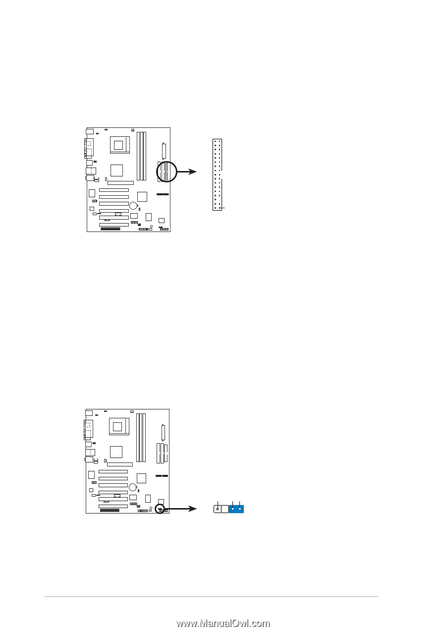
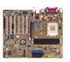
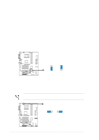
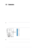
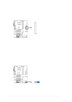
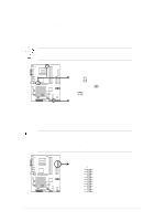
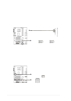
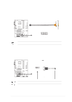
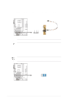
2. Floppy disk drive connector (34-1 pin FLOPPY) This connector supports the provided floppy drive ribbon cable. After connecting one end to the motherboard, connect the other end to the floppy drive. (Pin 5 is removed to prevent incorrect insertion when using ribbon cables with pin 5 plug). FLOPPY A7V600 ® NOTE: Orient the red markings on the floppy ribbon cable to PIN 1. PIN 1 A7V600 Floppy Disk Drive Connector 3. Chassis intrusion connector (4-1 pin CHASSIS) This lead is for a chassis designed with intrusion detection feature. This requires an external detection mechanism such as a chassis intrusion sensor or microswitch. When you remove any chassis component, the sensor triggers and sends a high-level signal to this lead to record a chassis intrusion event. By default, the pins labeled "Chassis Signal" and "Ground" are shorted with a jumper cap. If you wish to use the chassis intrusion detection feature, remove the jumper cap from the pins. CHASSIS +5VSB_MB Chassis Signal GND A7V600 ® A7V600 Chassis Alarm Lead (Default) 1-20 Chapter 1: Motherboard Information
-
 1
1 -
2
-
3
-
4
-
5
-
6
-
7
-
8
-
9
-
10
-
11
-
12
-
13
-
14
-
15
-
16
-
17
-
18
-
19
-
20
-
21
-
22
-
23
-
24
-
 25
25 -
 26
26 -
 27
27 -
 28
28 -
 29
29 -
 30
30 -
 31
31 -
 32
32 -
 33
33 -
 34
34 -
 35
35 -
36
-
37
-
38
-
39
-
40
-
41
-
42
-
43
-
44
-
45
-
46
-
47
-
48
-
49
-
50
-
51
-
52
-
53
-
54
-
55
-
56
-
57
-
58
-
59
-
60
-
61
-
62
-
63
-
64
-
65
-
66
-
67
-
68
-
69
-
70
-
71
-
72
-
73
-
74
-
75
-
76
-
77
-
78
-
79
-
80
-
81
-
82
 |
 |