Asus A7V600 A7V600 User Manual - Page 35
System Power LED Lead 3-1 pin PLED - x sata
 |
View all Asus A7V600 manuals
Add to My Manuals
Save this manual to your list of manuals |
Page 35 highlights
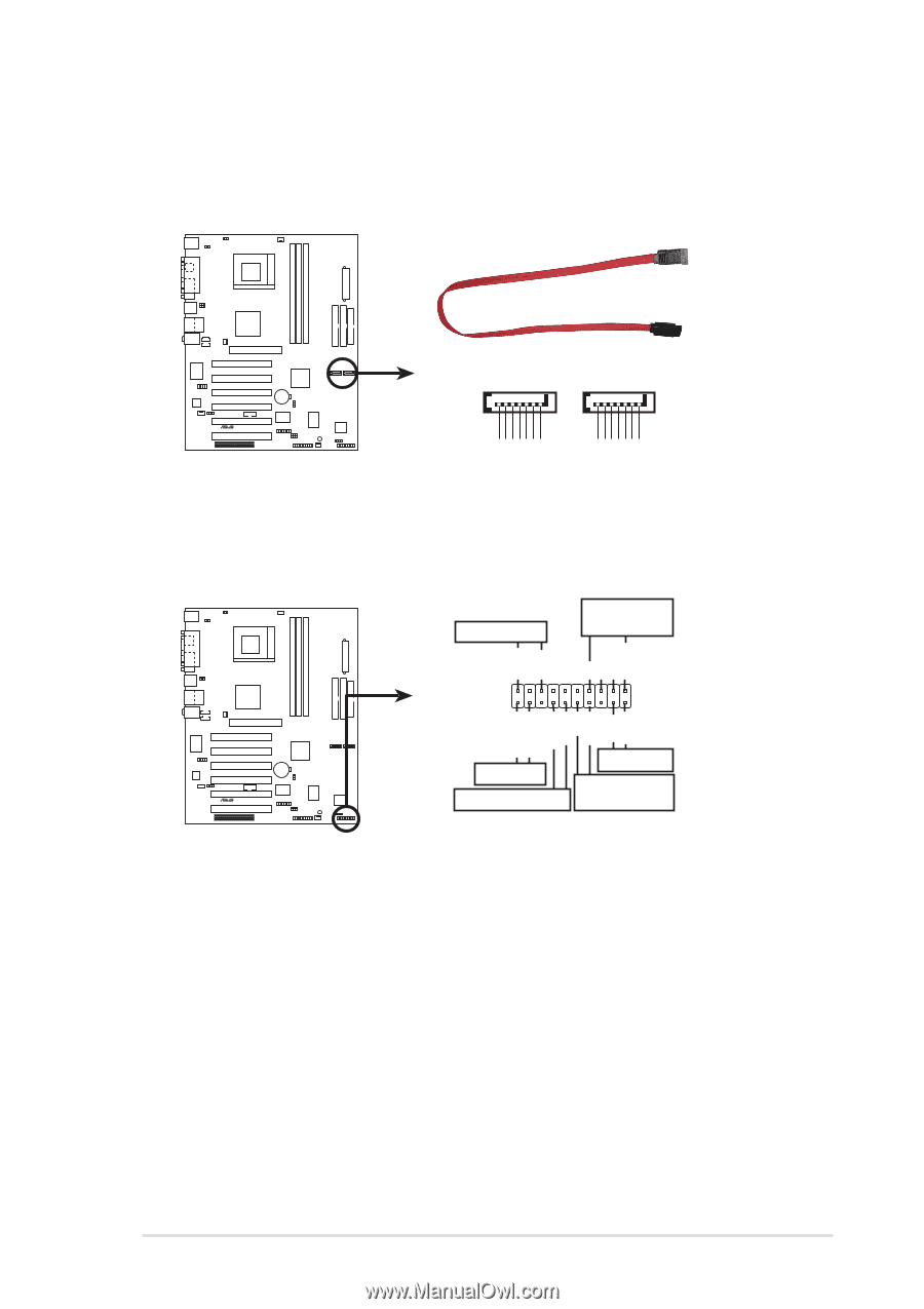
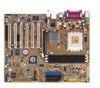
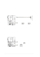
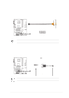
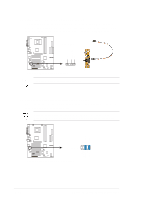
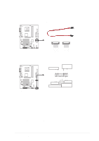
12. Serial ATA connector (7 pin SATA1, SATA2) These connectors accommodate the primary serial ATA (SATA1) and a secondary serial ATA (SATA2) cables. Connect the serial ATA cable to this connector then install to a serial ATA ready hard disk. A7V600 ® A7V600 SATA Connectors SATA2 SATA1 GND RSATA_TXP2 RSATA_TXN2 GND RSATA_RXP2 RSATA_RXN2 GND GND RSATA_TXP1 RSATA_TXN1 GND RSATA_RXP1 RSATA_RXN1 GND 13. System panel connector (20-pin PANEL1) This connector accommodates several system front panel functions. Power LED Speaker Connector PLED+ PLED+5V Ground Ground Speaker IDE_LED+ IDE_LED- ExtSMI# Ground PWR Ground Reset Ground A7V600 Reset SW IDE_LED ATX Power ® SMI Lead Switch* * Requires an ATX power supply. A7V600 System Panel Connectors • System Power LED Lead (3-1 pin PLED) This 3-1 pin connector connects to the system power LED. The LED lights up when you turn on the system power, and blinks when the system is in sleep mode. • System Warning Speaker Lead (4-pin SPKR) This 4-pin connector connects to the case-mounted speaker and allows you to hear system beeps and warnings. • Reset Switch Lead (2-pin RESET) This 2-pin connector connects to the case-mounted reset switch for rebooting the system without turning off the system power. ASUS A7V600 Motherboard 1-25
-
 1
1 -
2
-
3
-
4
-
5
-
6
-
7
-
8
-
9
-
10
-
11
-
12
-
13
-
14
-
15
-
16
-
17
-
18
-
19
-
20
-
21
-
22
-
23
-
24
-
25
-
26
-
27
-
28
-
29
-
 30
30 -
 31
31 -
 32
32 -
 33
33 -
 34
34 -
 35
35 -
 36
36 -
 37
37 -
 38
38 -
 39
39 -
 40
40 -
41
-
42
-
43
-
44
-
45
-
46
-
47
-
48
-
49
-
50
-
51
-
52
-
53
-
54
-
55
-
56
-
57
-
58
-
59
-
60
-
61
-
62
-
63
-
64
-
65
-
66
-
67
-
68
-
69
-
70
-
71
-
72
-
73
-
74
-
75
-
76
-
77
-
78
-
79
-
80
-
81
-
82
 |
 |